The BC-342 before cleaning. See below for results.
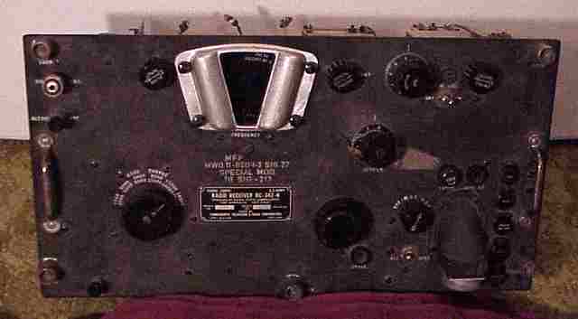
Signal Corps BC-342N receiver
The BC-342N is a WWII Army receiver with HF band coverage. Manufactured by Farnsworth, it is the 115 Volt AC version of the BC-312. It is quite heavy and was used primarily as part of field installations. The manual for the BC-342 and BC-312 series is TM-850 which is available in PDF form. The link to the PDF manual can be found on the home page.
In addition to the AC power supply, the BC-342 is wired for 12 volts for its tube filaments. The 9 tubes are wired so that three pairs of 6 volt tubes are wired in series. The audio output tube is a 6F6 which is in series with a pair of tubes, a 6C5 and a 6R7 along with a balancing resistor. The 12 volt DC versions of BC-312 use similar connections. Models of the BC-312 designed for 24 volts DC use sets of four 6 volt tubes each in the series filament strings. The audio output tube for those is a 12A6 which is in series with a resistor. All BC-312 used a dynamotor to supply B+ from the DC source.
Thoroughly checked the loose RF amp - converter section wiring. Re-connected several loose wires. Then did some resistance checks. Found the B+ line to be much lower resistance than expected. Traced it to the 2nd RF/converter bandswitch section with a big fat short when bands A, B, and C were selected. Proceeded to unsolder wires and pull that section by removing the bandswitch shaft and the subchassis according to the instructions in the manual. Opened the subchassis but did not find the short. Checked the now-unsoldered wire to the main tuning variable cap and found the stator shorted. After reconnecting the subchassis, tried to locate the tuning cap short since the spacing between the plates was OK. Finally removed the little shield cover plates on the cap (unique in this set?), and with a strong light, found the problem. The mounting bolt from the gear side of the cap was touching the stator connector that connects all of the stator plates together. Since that screw is horizontal and nearly impossible to get at without removing a number of components, began to wonder if this radio had ever worked properly. Possible factory defect? Couldn't get at the screw. Tried to move the stator a bit. All of the stator screws were still sealed with the original coating. Moving the stator did not remove the short. Finally used a hack saw blade to saw off the offending protruding threads from the mounting bolt. Short removed! (By the way, the B+ presence on two of the tuning cap stator sections is normal in these receivers when operating on the lower three bands. On the upper three bands, there is a series cap that keeps B+ off the tuning variable.)
Suspect that all of the miswiring and loose components found so far was an attempt by a former owner to solve the shorted tuning cap problem.
The B+ section overall still reads somewhat low in resistance. More reports later.
Update. Found another miswiring connecting the B+ line for the RF stages to the wrong tie point. Corrected the miswiring. Reconnected all loosened leads. Powered the unit up without the rectifier so as to test the tube filament connections. Found that the 6R7 second detector tube heated up too much and the 6F6 stayed rather cold. Opening the BFO shield revealed why, the 6C5 tube was missing. The 60 ohm balancing resistor was also burned out. The schematic shows the 6C5 and the 6R7 filaments in parallel and together in series with the 6F6. A 60 ohm resistor accounts for the differences in filament current between the tubes. The missing tube and open resistor caused most of the 12 volts of filament to go to the 6R7. More progess reports later
Replaced C-80, the 0.1 MF cap carrying B+, after determining that it was somewhat leaky. (Used a ceramic cap replacement but left original sealed cap in place.) Fed B+ from an external source to determine current draw. Appeared normal as the first signs of life came from the receiver. Alignment was way off as suspected and BFO dead. Reinserted the rectifier and metered the current draw and B+ voltage. Normal readings. (Manual says 0.7 amp draw from the AC line.) Proceeded to align the IF section on the crystal frequency. Then aligned the RF amp and converter sections. The lower 3 bands use normal oscillator settings of 470 KHz higher than the tuning dial markings but the upper three bands require the oscillator to be 470 KHz under the tuning dial. I used a little Radio Shack frequency counter to set the oscillator section and check tracking.
After proper alignment the set really came to life (except for Band "B" as noted below). The BFO also came to life after its alignment. Spent some time listening to amateur 20 meter SSB transmissions. Found the AVC not working and overloading on shortwave broadcasts. Traced the problem to a grounded IF coil return on the 2nd IF transformer. The line was touching a ground near the AVC/MVC control. Removing that short solved the AVC problem. All bands except "B" seem reasonably hot for the circuit and vintage. Will check Band "B" to see if there is any damage related to the shorted tuning cap.
Follow up
Thought that the coil for Band "B" in the 2nd RF/converter subchassis was open. Instead, found that the switch contact for that band was not touching properly. Suspect that the short circuit caused the contact to heat up and lose its spring temper. Bending it back a bit did not work. Will have to remove the rivet and replace the contact.
Final follow up
Used a Dremel tool to remove the rivet. Found the contact was OK. The rivet simply was not set in well causing the contact not to touch properly. Not sure if heating was the cause. Replaced the contact and used a small screw and nut to fasten it. Replaced the subchassis, tweaked the alignment, and enjoyed listening to SSB on 80 meters on Band "B" on the now fully functioning set.
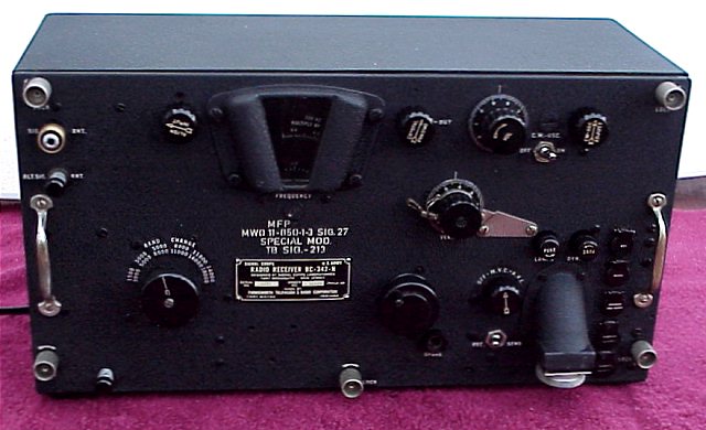
Most of these sets show wear on the tuning knob paint. This one does not. Also, the little phone jack covers are often bent or missing. Suspect that all of the problems in this set caused it to stay in storage these many years and kept it in decent cosmetic condition from lack of use. After cleaning, the front panel was nearly pristine. The tuning dial cover had had its paint removed. I suspect it had been swapped before I purchased it. I swapped it for another and will eventually paint it as part of another BC-342 restoration.
The nomenclature tag.
MFP is "Moisture Fungus Proofing". MWO stands for "Modification Work Order". SIG is "Signal Corps"
TB SIG-213 is a Signal Corps Technical Bulletin. For example, TB SIG-13 discusses MFP.
Do not know title or content of TB SIG-213.
Have no idea what the "Special Mod " refers to. Write me if you know.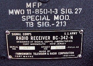
The Navy DAE-1 Radio Direction Finder was the previous item on the bench.