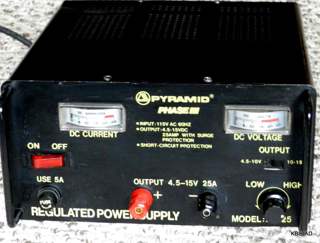
Having gotten some good feedback from folks reading my website, I have decided to add my experiences with another high current low voltage supply commonly used with modern transceivers, this time a Pyramid Phase III PS-25 that has variable voltage output and is capable of 25 amps current.
Note that the 25 amp rating is definitely not for continuous use. Like the previous Pyramid PS-21KX and all such linear power supplies, this one is heavy with the large transformer inside. The unit has both an ammeter and a voltmeter. The supply is designed to be controlled by the front panel "low-high" control for variable voltage output with two selectable ranges of 4.5 to 10 volts and 10 to 15 volts via the slide switch marked "output". Unlike the Pyramid PS-21KX, this one has an adjustable crowbar circuit on a separate board.
Many of the Pyramid schematics do not have the component values listed on them. Refer to the PS-21KX schematic (bottom of page) of the previous Pyramid for some of the component values. The PS-25 schematic also does not show the selectable voltage taps on the transformer.

On this particular Pyramid, the lower voltage range on the front panel slide switch selects a tap on the power transformer primary which in turn reduces the voltage output of the transformer secondary. The purpose of the lower transformer voltage is to reduce the power requirement and heating of the pass transistors when a lower voltage is needed at high current. Any excess voltage at high current must be shed by the pass transistors as heat. Therefore less voltage fed to the transistor collector connections at a given current means reduced heating.
Checking out the circuit.
The heart of this power supply like most ham radio linear power supplies, is the little LM-723 regulator. See the
previous Pyramid PS-21KX repair
for more information on the LM-723. The one in the PS-25 is socketed, allowing easy replacement of this very inexpensive 14 pin chip.


The crowbar circuit.
The typical crowbar circuit in this Pyramid and in Astron power supplies is an SCR that is activated by over-voltage, short circuiting the output which then typically blows the fuse or kicks in the current-limiting function of the LM-723. See the "over-voltage protector" circuit on the PS-25 schematic. The fuse must not be larger than the recommended size. Substituting a larger fuse will no longer provide full protection for the supply. I have seen Astron power supplies with a burned-out hole in the circuit board because the SCR heated up and was destroyed trying to short out a power supply with a too-large fuse.
The SCR is activated by a zener diode and a resistor divider network. The trigger point on the Pyramid is adjustable. An increase in voltage at the output, typically in the range of 15 to 16 volts, will cause the zener to trigger the gate of the SCR. The SCR which is normally rated at the maximum ampere capability of the power supply is wired across the output of the supply and conducts at the trigger voltage.
Troubleshooting; no voltage, fuse blown
Check to see if the crowbar circuit was activated. Disconnect the wire from the positive output connection to the crowbar SCR and replace the fuse. Measure the voltage at the collectors of the pass transistors with the negative prod of the meter at the negative output terminal. The metal body of a transistor in a TO-3 case is connected to the collector. The voltage at the collectors (and the transistor cases) should be the unregulated DC voltage of 20 volts or more. If there are no volts there, the problem is in the rectifier or transformer, a rare occurrence.
Assuming 20 volts or more at the collectors, measure the voltage at the output of the power supply. If the voltage is too high (more than the design maximum of 14 to 15 volts at no load) chances are that the pass transistors are shorted or leaky causing the SCR crowbar to short out the supply and the fuse to blow. Check the pass transistors. If there is no voltage at the output but 20 or more at the collectors, then check the bases of the pass transistors for voltage. If no volts there, check for voltage at the output pin 10 of the LM-723. If no volts there, replace the LM-723 chip. Note that we skipped the lone 2N3055 inside the supply since it is the least likely to fail.
Troubleshooting; no voltage at output, proper size fuse not blown
I usually find the LM-723 chip dead when the supply fails and a proper-sized fuse is not blown. I check to see if the non-regulated portion of the supply is working as described above by measuring the voltage at the pass transistor collectors and the negative terminal. Also check for shorts at the output to see if the over-current function has kicked in.
If the non-regulated portion of the supply is working and there are no shorts on the output, a quick voltage check at pin 10 will verify whether the chip is in fact functional. That voltage would normally be the intended output voltage plus any voltage drops (of the PN junctions of the 2N3055 first amplifier (inside the supply), the 2.2 ohm base balancing resistors and the base to emitter PN junctions of the four 2N3055 pass transistors.)
Repairs to this power supply
The unregulated power of this Pyramid was in good condition as was the fuse. I found a dead LM-723 chip. All five of the 2N3055 transistors were in good condition. Replacing the LM-723 chip was all the repair that was needed. I cleaned the on-board pots and the front panel voltage control with contact cleaner and then also added a MOV across the power line after the fuse and power switch since I suspected that a spike on the power line had caused the LM-723 to fail. An alternate solution is to simply plug the Pyramid into a late-model UL and CSA approved surge protector which has the MOVs included. (Late model surge protectors use fused MOVs in case of catastrophic breakdown in the MOVs themselves.)
A load test with several car headlights verified a fully functional power supply.
Testing the Pyramid crowbar circuit
The little crowbar circuit board in the Pyramid has a heavy red wire that goes directly to the positive output terminal.

I later spliced the cut wire with a wire nut making it easier to open the circuit and test again in the future.
Current limiting
The supply is wired for current limiting so that a short circuit will shut the unit down as sensed by the LM-723 chip. It worked quite well. In fact, when I connected several car headlight lamps as a load that would normally take about 25 amps, the shut down circuit kicked in. That was because of the cold filaments of the lamps which look like a short circuit until they are warmed. I could connect the full lamp load by connecting a couple of headlights and then adding the others. The current limiting (circuitry to pin 2 of the LM-723) is adjustable but was working as expected. Assuming the current limiting is working properly, a crowbar short would just shut down the power supply without opening the fuse, requiring just a power down and then on again for a reset after the short or excess load is removed.
Pyramid Design
All of the Pyramid pass transistors are soldered-in with no sockets. I consider that a design weakness that makes repairs difficult. Like the previous Pyramid PS-21KX supply, we find a 2.2 ohm resistor in series with each pass transistor base. The Astrons and most other supplies use a resistor such as a 0.1 ohm in each emitter leg. The purpose of those resistors is to balance the load of the four pass transistors. I prefer the use of a balance resistor in the emitter side rather than the base, but the Pyramid circuit seems to work fine.
On the other hand, I like the use of three separate circuit boards for the electrolytics, the 723 chip, and the crowbar and that the circuit includes several capacitors in critical locations to protect from stray RF. The Pyramid's current limiting function also worked well.

date: 3-13-15
A Heathkit HD-1416 Code Practice Oscillator was the previous item "on the bench".