I've been interested in the class A Climax logging locomotives for a long time, but could never find enough information to adequately model one until I discovered The Climax Locomotive six months ago. This magnificent 497 page volume, published by Oso in Hamilton, Montana, is a treasure of rare and wonderful photos, authoritative history, first-hand accounts, technical details, drawings, and much more. It wasn't long before I decided to make a gauge 1 model of a vertical boiler class A.
Although I have made a few live steam engines over the years, I have a special affection for the stirling engine, and decided that my class A would be stirling-powered. Four years ago I completed a gauge 1 model of a four wheel Swiss rail car that was powered by an alcohol-fired stirling engine for long runs, and by compressed air supplied to its steam engines for short demonstration runs (Modeltec magazine, March-April 2002). Now I wanted to revisit the stirling-powered locomotive idea, this time incorporating a gearbox to provide forward, idle, and reverse, with remote control through the track. The aim was to create an unusual, attractive, and practical fire-driven locomotive for a garden railway.
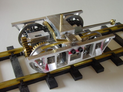
It seemed reasonable to begin with the trucks, since all the other parts rest upon them. I started with some wheels and axles from Hartford Products, then re-machined the wheels' contours and milled out sixty-four little spokes. How to drive those wheels became the next question. Climax used driveshafts located along the locomotive's center-line to transmit power from a marine-style steam engine to the trucks. These driveshafts passed over the axles, driving them with skew gears, which are similar to bevel gears except their shafts are not in the same plane. As I could find no source for such gears, I used stock bevel gears in combination with a pair of helical gears to raise the input shafts above the axles. By locating these gears on the outboard ends of the trucks, the driveshaft connection for each truck could be located immediately below the swivel joint for that truck, minimizing both lateral and fore and aft driveshaft motion. The "universal" joints here are simply lengths of silicone rubber model airplane fuel line fitted over the shafts. The two remaining axles are driven by small plastic sprockets and chain from the gear-driven axles. All axles are sprung independently.
A simpler approach to all-wheel drive would omit powering the trucks' second axles, but rather let those axles float with very light springs, so essentially all the machine's weight would be borne by the two driven axles. The resulting cantilevered forces on the truck bolsters would need to be addressed, of course, but the trucks would be significantly easier to make.
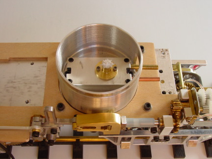
The transmission of power from the stirling engine to the trucks is as follows: A standard rubber O-ring transmits power from a pulley on the engine to a larger pulley on a countershaft. This is a high speed, low torque connection, and there has been no sign of any slippage. The countershaft has a small brass pinion gear, which is the heart of the gear shift mechanism. Below this pinion is a pivoting yoke, containing a train of three brass idler gears. The top two of these gears are located so that one, or the other, or neither, will engage with the countershaft pinion as the yoke is pivoted to and fro on an axle concentric with its bottom (third) gear. This is the same arrangement used on many lathes to provide forward, reverse and neutral to the lead screw. In my model one more gear provides further speed reduction, and drives a set of miter gears which turn the power 90 degrees to align with the driveshafts. It is here that the true universal joints are used. They are of the simplest type, merely a cup with a slot engaging a ball with a pin. These allow for any fore and aft, and angular, movement of the drive-shafts.
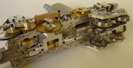
The gears are shifted from forward to neutral to reverse and back by means of a small motor and reduction drive unit (a hobby shop item) connected to a screwjack by yet more silicone rubber fuel line, which provides a necessary high-torque slip clutch for the drive.
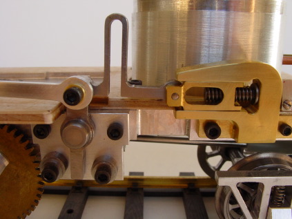
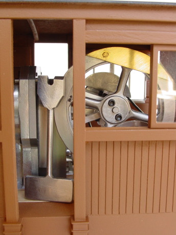
The pivoting yoke needs firm stops to prevent its gears from being driven too far into the countershaft pinion. These are provided by routing the yoke's drive linkage through a steel lever with adjustable steel stops. But the overall rigidity of the drive system would occasionally force the shifting gears together on their outer diameters, rather than in mesh, thereby greatly increasing friction and stalling the engine. Filing the mating gear teeth to a sharper profile, so there would be less likelihood of their outside diameters colliding, minimized but did not solve the problem. Putting a stiff spring (in this case, an oxbow machined into the connecting rod) between the screwjack and the stop lever did solve the problem. The transmission now works smoothly and reliably; but as with the trucks, I do believe a much simpler and more elegant approach could be devised.
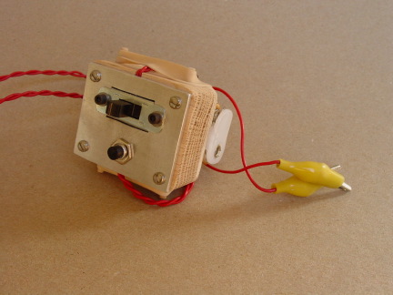
The controller for this shifter is a handheld battery box with a reversing switch and a button, and two leads that are attached to the track. The button controls when the current can flow to the servo motor in the locomotive, and the reversing switch controls which way the motor (and therefore the shift linkage) moves. Idle is between the stops of forward and reverse, and it requires a fairly deft finger on the button to stop the shift linkage during the brief time when neither gear is engaged with the pinion. Forward and reverse are easy to engage by merely driving the mechanism to its stops, whereupon the slip clutch lets the motor continue to turn until the operator removes his finger from the button.
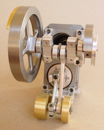
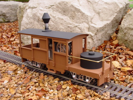
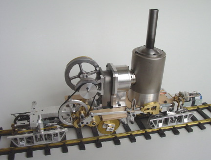
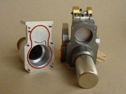
The stirling engine is quite similar to the one I made for the Swiss railcar. It is a two piston (or alpha) type stirling, in which the pistons are linked together so the motion of one leads that of the other by 90 crankshaft degrees. They move in separate parallel cylinders that are connected together by a long annular passage that is divided into three sections of heat exchangers. The section next to the expansion (or "hot") cylinder of the leading piston is the externally-fired heater. The section next to the compression (or "cold") cylinder of the trailing piston is the heat-dissipating cooler. The section of the annular passage between the heater and cooler is heated or cooled only by the gas flowing through it, not by external means. This section serves as a regenerator, which is a heat-conserving device invented by Robert Stirling in 1816. It is interesting to note that the engine bearing Stirling's name was merely one of several ingenious ideas he suggested to illustrate how his regenerator might prove useful.
This arrangement of parts cooperates to accomplish the following four things during each crankshaft revolution:, 1) compress the working gas when most of it is in the cold cylinder and its temperature and pressure are low; 2) transfer most of the working gas through the heat exchangers to the hot cylinder, thereby raising its temperature and pressure; 3) expand the working gas when most of it is in the hot cylinder and its temperature and pressure are high; and 4) transfer most of the working gas through the heat exchangers to cool cylinder, thereby lowering its temperature and pressure. Expanding the high pressure gas produces more power than is consumed by compressing the same gas at a lower pressure, and this excess power is the engine's output. Of course there are many subtleties, but this is the essence of the stirling cycle engine.
The crank drive mechanism is my own design, which I call the Rocker V mechanism because it uses one rocking piston and is balanced like a V-twin. A nice schematic of this simple, strong, and readily-balanced mechanism may be found on Izzy Urieli's web site.
But making a robust model stirling engine depends not so much on choosing the right cylinder arrangement or drive mechanism as it does on; 1) keeping friction very low, 2) keeping internal dead volume low and compression ratio high, 3) making pistons that seal really well, and 4) providing enough surface area for the heat exchangers to transfer heat to and from the working gas rapidly.
Rather than having cooling fins, the engine simply has its cooler section screwed down to the massive aluminum alloy frame, which serves as a heat sink to dissipate waste heat. The burner for the new engine has only 44% of the wick area of the railcar engine, and therefore burns about 44% of the fuel, or about one cubic centimeter of alcohol for each nine minutes of operation. The burner holds ten cubic centimeters when filled. Warm up takes about one minute after light-up.
Less wick area of course means less power; this difference is made up by a lower overall gear ratio used in the Climax and its fully sprung all-wheel drive. The railcar has only two of its four wheels driven, and they are unsprung. Overall weights are similar, with the Climax weighing 2.3 Kg (5.07 pounds) and the railcar 2.39 Kg (5.25 pounds). Trials showed the Climax would make 550 grams of pull when tethered to the scale compared to the railcar's 300 grams. Both machines spin their wheels when restrained.
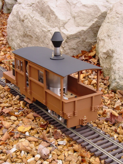
One of the interesting challenges was machining the underside of the little piece that slips over the stack and rests on the curved roof, holding the safety valve and whistle. The radius of this curve is just over 9 inches, and I had no easy way to cut it directly; but the job was readily done with just 8 trigonometrically-calculated step cuts per side with an eighth inch end mill. The tiny steps didn't even need to be filed smooth; the part just fit and clung to the roof perfectly when aligned correctly.
Other interesting parts included the window frames, since their mullions were so long and thin. They were machined (very carefully!) out of aluminum alloy, and their round corners were then filed square. I also had to consider how to flip the crankshaft over to start the engine, since it was within a wooden cabin. This task became easy after recalling that the flywheel was attached to the crankshaft by being screwed to a clamp mounted behind it. Although these screws were recessed into the flywheel's hub, the hub was easily milled down to expose enough of the screws and crankshaft to permit engaging them with a starting key poked through the open starboard window.
Over the course of building this model there were many modifications and revisions, both major and minor, which I have not described here. The biggest change was in the wooden flatcar and cabin. Originally I modeled an open cabin prototype, but the stirling engine looked far too large to create any illusion of reality. Moreover, the wooden structure could not be removed to get at the mechanical parts without first dismantling the entire transmission.
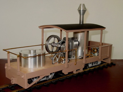
Since the class A Climaxes were built in so many variations, and modified so routinely by their owners, it was easy to find a suitable enclosed prototype to convert my model into. The new wooden structure is attached to the aluminum alloy frame with just four screws, and may be removed without removing any of the mechanical components.
At last the modifications are complete, and I am now satisfied with the model, both mechanically and aesthetically. Of course that doesn't mean it won't get modified again, sometime in the future. I consider most of my projects to be experimental works-in-progress; and that attitude seems particularly appropriate for a model of a class A Climax.