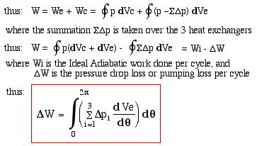
Chapter 5d - Pumping Loss Simple Analysis
Throughout this analysis we have assumed that at any
instant the pressure is constant throughout the engine. However we
find that the high heat fluxes required in the heat exchangers in
turn requires a large wall/gas, or wetted area Awg. This requirement
together with the conflicting requirement of a low void volume will
result in heat exchangers with many small diameter passages in
parallel. The fluid friction associated with the flow through the
heat exchangers will in fact result in a pressure drop across all the
heat exchangers which has the effect of reducing the power output of
the engine. This is referred to as the "Pumping Loss" and
in this section we attempt to quantify this power loss. We first
evaluate the pressure drop across all three heat exchangers with
respect to the compression space. Subsequently we can determine the
new value of work done by integrating over the complete cycle, and
isolate the Pumping Loss term as follows:
The
pressure drop Δp is due to fluid friction as it flows through the
heat exchanger sections. Our model has assumed one-dimensional flow
throughout, however the fundamental concepts of fluid friction
paradoxically break down under one-dimensional flow. Newton's law of
viscosity states that the shear stress τ between adjacent layers of
fluid is proportional to the velocity gradient (du/dz)
in these layers normal to the flow direction, as shown:

From
the equation we see that a Newtonian fluid cannot sustain a shear
stress unless the flow is two dimensional. This paradox is bypassed
by stating that the flow is not strictly one-dimensional, but rather
represented by its mean bulk mass flow rate. The dynamic viscosity μ
is basically a measure of the internal friction which occurs when the
molecules of the fluid in one layer collide with molecules in
adjacent layers travelling at different speeds, and in so doing
transfer their momentum.
Over the pressure range of interest the dynamic
viscosity μ is independent of pressure. Its temperature dependence
for the gasses of interest is obtained as in the diagram below
(Refer: Bretsznajder, A, 1971, "Prediction of the transport and
Other Physical Properties of Fluids", International Series of
Monographs in Chemical Engineering, II, Oxford: Pergamon)

The frictional drag force F is related to the shear
stress τ as follows:
F = τ Awg
where Awg is the wall/gas, or wetted area of the heat
exchanger.
In setting up the working expressions to describe
pumping loss we introduce the concept of a "hydraulic diameter"
d, which describes the ratio of the two important variables of a heat
exchanger - the void volume V and the wetted area Awg:
d = 4 V / Awg
The factor 4 is included for convenience. For flow in
a circular pipe ( or a homogeneous bundle of circular pipes) the
hydraulic diameter thus becomes equal to the pipe internal diameter.
Substituting in the force equation above:
F = 4 τ V / d
We now define a Coefficient of Friction Cf as the
ratio of the shear stress τ to the "dynamic head" (Refer
to "Compact
Heat Exchangers", Kays &
London):

where ρ is the fluid density and u is the fluid bulk
velocity. Thus substituting for τ in the force equation we obtain
the frictional drag force in terms of the Coefficient of Friction:

Under the quasi-steady flow assumption (no
acceleration or deceleration forces) the frictional drag force is
equal and opposite to the pressure drop force, thus:
F + Δp A = 0
where A is the cross sectional (free flow) area.
Substituting for F, the pressure drop Δp is given by:

Note that Δp can be positive or negative, depending
on the direction of flow. However the second term in this equation is
always positive, and thus the equation violates the momentum
conservation principle in the case of reversing flow. We resolve this
by defining a "Reynolds Friction Coefficient" (Cref) by
multiplying the Reynolds Number by the Coefficient of Friction as
follows:
Cref = Nre Cf
Where Nre = ρ u d / μ is the Reynolds Number,
defined and discussed in the section Scaling
Parameters. By definition, the Reynolds
Number is always positive, independant of the direction of flow. Thus
finally:

This equation satisfies the momentum conservation
principle for both positive and reversed flow, since the sign of Δp
is always correctly related to the sign of the velocity u. Since all
current empirical data on the Coefficient of Friction is presented as
a function of Reynolds Number, it is a simple matter to convert that
data to the required Reynolds Friction Coefficient. For example, the
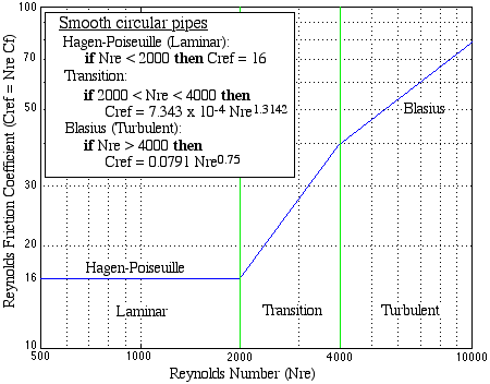
Coefficient of Friction vs Nre curves for circular pipes (Moody
Diagram) have been in widespread use over the past half a century.
These curves have been simplified and rearranged in terms of the
Reynolds Friction Coefficient Cref as follows:
Similar formulations can be done for the various heat
exchanger and regenerator types of interest. (Refer to "
Compact
Heat Exchangers", Kays &
London).
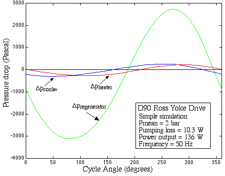
The Simple simulation of our D90 Ross Yoke-drive
engine case study results in the following pressure vs crankangle
plots. The first plot shows the pressure drop across the three heat
exchangers. Note the relative magnitude (as well as the phase) of the
regenerator pressure drop with respect to those of the heater and
cooler.
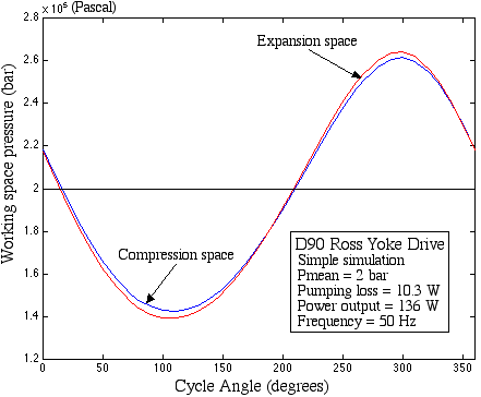
The following plot shows the expansion and
compression space pressures vs crankangle. Under these conditions the
pumping loss is 10.3 W, or about 7.5% of the net output power.
The complete simulation package including the
pressure drop (pumping) loss, heat transfer and regenerator loss is
described in the following section "Function set 'simple'".
______________________________________________________________________________________

Stirling Cycle Machine Analysis by Israel
Urieli is licensed under a Creative
Commons Attribution-Noncommercial-Share Alike 3.0 United States
License