One approach to increasing the efficiency of steam power cycles is by extracting some of the steam from various stages of the turbine and using it to preheat the compressed liquid before it enters the boiler. This is done either by direct mixing of the fluids (Open Feedwater Heater) or through a heat exchanger (Closed Feedwater Heater) – refer: Feedwater heater. In many practical steam power plants various combinations of open and closed feedwater heaters are used, and systems using them are generally referred to as Regenerative Cycles.
We continue with the Reheat cycle developed in Chapter 8a and examine the performance effects of adding open and closed feedwater heaters.
The Ideal Regenerative Reheat Cycle using an Open Feedwater Heater
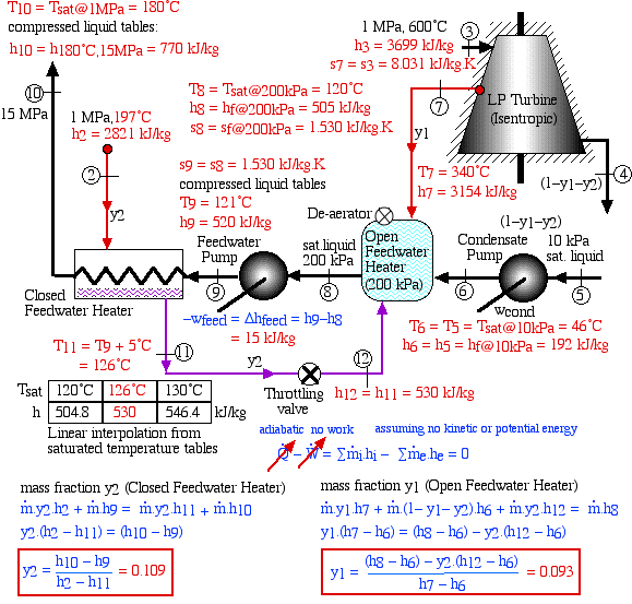
We continue with the Reheat cycle developed in Chapter 8a, and examine the effect of adding a regenerative heat exchanger in the form of an Open Feedwater Heater, as shown below. We will find that this system does result in an increase in thermal efficiency by preheating the water before it enters the boiler, however at the expense of a reduced power output. In the schematic diagram we notice that many of the state and enthalpy values (indicated in red) have already been evaluated in Chapter 8a. The mass fraction of the steam bled at the outlet of the HP turbine (2) as well as the state and enthalpy values at stations (6) through (9) will be evaluated below.
For this example we have chosen the mixture pressure of the open feedwater heater as 200kPa. Notice that a portion of the steam is bled off the outlet of the HP turbine at a pressure of 1MPa, passed through a throttling valve reducing its pressure to 200kPa, and then mixed with the compressed liquid (also at 200kPa), ultimately resulting in saturated liquid at station (8). We first need to determine the mass flow fraction y of the bled steam required to bring the output of the open feedwater heater (8) to a saturated liquid state.
Notice that the work output is reduced by having bled off a fraction y of the steam, and the boiler heat input is reduced by the increased temperature of the compressed liquid entering the boiler T9. Thus:
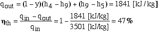
We always confirm our results by the alternate evaluation of efficiency using the heat flow out from the condenser to the cooling water:
Thus we see a slight increase in efficiency and reduction in power compared to the reheat system that we solved in Chapter 8a (45%, 1910 kJ/kg). Can we justify this added complexity for such a small gain in efficiency? This was discussed in Solved Problem 4.2 in which we noted that a de-aerator is a necessary vital component of a steam power plant, since without it the dissolved oxygen and carbon dioxide in the feedwater can cause serious corrosion damage in the boiler. The open feedwater heater naturally includes a de-aerator. On a previous visit to the Gavin power plant we were informed that the open feedwater heater can also conveniently include a liquid water storage tank which enables the feedwater pump to be the main power control of the system by varying the mass flow rate of the steam. We were also informed that using a single feedwater pump to increase the water pressure from 10 kPa to 15 MPa is impractical, and in the Gavin power plant, in addition to the condensate pump there is a booster pump to bring the pressure from 10 kPa to the de-aerator pressure.
Problem 8.1 - A 10 MPa Steam Power Plant with an Open Feedwater Heater
Problem 8.2 - A Cogeneration Steam Power Plant with an Open Feedwater Heater
________________________________________________________________________
The Ideal Regenerative Reheat Cycle using a Closed Feedwater Heater
We again extend the Reheat cycle developed in Chapter 8a, and examine the effect of adding a regenerative heat exchanger in the form of a Closed Feedwater Heater, as shown below. We have not included an open feedwater heater even though we learned in the previous example that it is a necessary component of a high pressure steam cycle, since we are using this example to develop the techniques for analyzing closed feedwater heaters. The various state values shown on the schematic (in red) have been evaluated in previous sections.
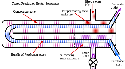
From the schematic diagram we see that a portion of the steam is bled off from the output of the HP turbine at state (2), and then used to heat the high pressure liquid, ultimately condensing to a subcooled liquid at state (8). A finite temperature difference is a necessary condition for heat transfer to occur, and from the temperature distribution plot shown above we see that the closed feedwater heater behaves as a counterflow heat exhanger, in which the compressed liquid water entering at state (6) is heated to the saturation temperature of the bled steam (Tsat@1MPa = 180°C). In typical closed feedwater heaters (such as those used at the Gavin Power Plant) there are three distinct zones of heat transfer as shown in the simplified schematic diagram below:
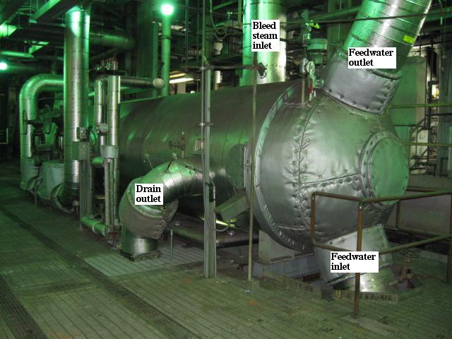
The bled steam first enters the desuperheating zone enclosure and is cooled while raising the temperature of the feedwater leaving the heater to a level approaching or equal to the steam saturation temperature. The condensing zone is the largest heat transfer region within the heater shell. The major portion of heat transfer takes place here as the steam condenses and gives up its latent heat. The subcooling zone, which is enclosed in a separate shrouded area within the shell, further cools the condensed steam while heating the incoming feedwater. The following photograph shows one of the seven sets of closed feedwater heaters used in the Gavin Power Plant Typically we find that the subcooled liquid is reduced to within around 4°C to 6°C above the incoming feedwater temperature.
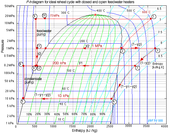
The P-h diagram plot of this system follows, and we notice on the diagram that the high pressure feedwater is heated from state (6) to state (7) before entering the boiler, while a mass fraction y of the bled steam is cooled from the HP turbine outlet state (2) to a subcooled liquid at state (8). The subcooled liquid is then passed through a throttling valve before being returned to the condenser at state (9). As we have learned from our studies of refrigerators, a throttling valve is simply represented on the P-h diagram by a vertical line, since from the energy equation we find that h8 equals h9.
We consider first the evaluation of the mass flow fraction y, which is bled from the output of the HP turbine on order to heat the compressed water at state (8) to the saturation temperature of the steam at station (2):
Once again we notice that the work output is reduced by having bled off a fraction y of the steam, and the boiler heat input is reduced by the increased temperature of the compressed liquid entering the boiler T7. Thus:
Thus the system thermal efficiency becomes:
The alternative evaluation of thermal efficiency using the heat transfer from the condenser to the cooling water:
Notice that the thermal efficiency is slightly more than that of the previous example with an open feedwater heater, however with even less power output. In practice one normally finds a combination of open and closed feedwater heaters, and in the Gavin power plant there are seven closed feedwater heaters and one de-aerator/open feedwater heater. In the following section we develop the analysis technique of this type of system.
Problem 8.3 - A Reheat Steam Power Plant with a Closed Feedwater Heater
________________________________________________________________________
The Ideal Regenerative Reheat Cycle using both an Open and a Closed Feedwater Heater
In a practical power plant one may find various combinations of closed and open feedwater heaters. For example the Gavin Power Plant has one open- and 7 closed-feedwater heaters in each of the two sections of the plant (refer to the Case Study at the end of this section). In the following example we have chosen one open and one closed feedwater heaters in order to illustrate the method of analysis, however the same approach will apply to any combination of feedwater heaters.
Once again we evaluate the required mass flow fractions y1 and y2 of the bled steam in order to bring the compressed water at the entrance to the boiler (state (10)) to the correct state. An enthalpy inventory and energy balance on both the closed and open feedwater heaters leads to the following:
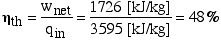
The resultant net work output and heat input now become:
And finally we obtain the thermal efficiency of the overall system as follows:
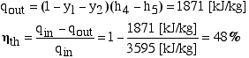
As always, we check this result against the equivalent method of considering only heat in and heat rejected in the condenser to the cooling water
.
Case Study - The General James M. Gavin Steam Power Plant
______________________________________________________________________________________
![]()
Engineering Thermodynamics by Israel
Urieli is licensed under a Creative
Commons Attribution-Noncommercial-Share Alike 3.0 United States
License