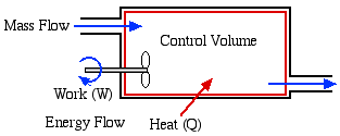
In this course we consider three types of Control Volume Systems - Steam Power Plants, Refrigeration Systems, and Aircraft Jet Engines. Fortunately we will be able to separately analyse each component of the system independent of the entire system, which is typically represented as follows:
In addition to the energy flow across the control volume boundary in the form of heat and work, we will also have mass flowing into and out of the control volume. We will only consider Steady Flow conditions throughout, in which there is no energy or mass accumulation in the control volume, thus we will find it convenient to derive the energy equation in terms of power [kW] rather than energy [kJ]. Furthermore the term Control Volume indicates that there is no boundary work done by the system, and typically we have shaft work, such as with a turbine, compressor or pump.
Consider an elemental mass dm flowing through
an inlet or outlet port of a control volume, having an area A, volume
dV, length dx, and an average steady velocity
![]() ,
as follows.
,
as follows.
Thus finally the mass flow rate
![]() can be determined as follows:
can be determined as follows:
The fluid mass flows through the inlet and exit ports of the control volume accompanied by its energy. These include four types of energy - internal energy (u), kinetic enegy (ke), potential energy (pe), and flow work (wflow). In order to evaluate the flow work consider the following exit port schematic showing the fluid doing work against the surroundings through an imaginary piston:
It is of interest that the specific flow work is simply defined by the pressure P multiplied by the specific volume v. In the following section we can now develop the complete energy equation for a control volume.
Consider the control volume shown in the following
figure. Under steady flow conditions there is no mass or energy
accumulation in the control volume thus the mass flow rate
![]() applies
both to the inlet and outlet ports. Furthermore with a constant mass
flow rate, it is more convenient to develop the energy equation in
terms of power [kW] rather than energy [kJ] as was done previously.
applies
both to the inlet and outlet ports. Furthermore with a constant mass
flow rate, it is more convenient to develop the energy equation in
terms of power [kW] rather than energy [kJ] as was done previously.
The total power in due to heat and mass flow through the inlet port (1) must equal the total power out due to work and mass flow through the outlet port (2), thus:
The specific energy e can include kinetic and potential energy, however will always include the combination of internal energy (u) and flow work (Pv), thus we conveniently combine these properties in terms of the property enthalpy (as was done in Chapter 3a), as follows:
Note that z is the height of the port above some datum level [m] and g is the acceleration due to gravity [9.81 m/s2]. Substituting for energy e in the above energy equation and simplifying, we obtain the final form of the energy equation for a single-inlet single-outlet steady flow control volume as follows:
Notice that enthalpy h is fundamental to the energy equation for a control volume.
When dealing with closed systems we found that sketching T-v or P-v diagrams was a significant aid in describing and understanding the various processes. In steady flow systems we find that the Pressure-Enthalpy (P-h) diagrams serve a similar purpose, and we will use them extensively. In this course we consider three pure fluids - water, refrigerant R134a, and carbon dioxide, and we have provided P-h diagrams for all three in the Property Tables section. We will illustrate their use in the following examples. The P-h diagram for water is shown below. Study it carefully and try to understand the significance of the distinctive shapes of the constant temperature curves in the compressed liquid, saturated mixture (quality region) and superheated vapor regions.

______________________________________________________________________________
______________________________________________________________________________________
![]()
Engineering
Thermodynamics by Israel
Urieli is licensed under a Creative
Commons Attribution-Noncommercial-Share Alike 3.0 United States
License


