Navy DAE-1 Radio Direction Finder
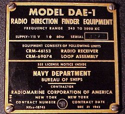
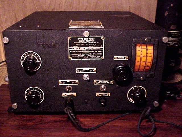
The Navy DAE-1 is a World War II era radio Direction Finder system. The Navy identifies the receiver as part number CRM-46153 and the loop as part number CRM-69074. The Contract date December 31, 1942. With the loop antenna, this direction finding equipment was used to locate radio transmitters and signals both friendly and clandestine. The frequency coverage is 240KHz to 2000 KHz in 3 bands. Manufacturer was RMCA, the RadioMarine Corporation of America.
The radio is a single conversion superhet with two 175KHz IF stages and one RF stage. The volume control is actually an RF gain control. Due to its direction-finding function, it does not have AVC.
Repair notes: This unit was cleaned thoroughly and was in decent cosmetic shape inside and out except for some paint scrapes on the cabinet top. The cabinet is high quality copper clad steel.
After a thorough safety check, did some unpowered tests. Found the audio output transformer primary open. Found a near exact replacement (it had a couple of extra taps on the secondary) in my "junk box".
Further checks found the coax cable open in one of the two leads. (This is an early form of Twinax). Used a Sencore capacitance meter to determine roughly the location of the break which was about 10 inches from one of the connectors. Removed those ten inches and repaired the shortened cable. After a slow power-up, the unit is working but sensitivity semed to be lacking somewhat.
Repair follow-up: Loss of sensitivity was due to poor alignment of the first IF. Did a through alignment including the front end for each band. Those adjustments made a significant difference. The IF is 175 KHz. The audio passband at that low IF is a bit limited but the greater selectivity is very noticeable. I replaced the slightly leaky input capacitor to the 6C5 audio output tube. The AC line filter caps tripped the bench GFCI so I replaced those with somewhat reduced capacitance. The original sealed caps were left in place for cosmetic purposes.
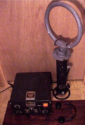
After I was satisfied with the performance, I had a lot of fun listening to distant Broadcast stations while turning the direction finder antenna for maximum signal at minimum interference. I also picked up 160 meter ham SSB transmissions. The audio output is designed for a 600 ohm impedance head set. It will drive a loudspeaker with the proper matching transformer but output is limited. I connected a matching transformer and speaker and also fed the output into an external audio amplifier. Using a simple load resistor and then feeding an external audio amp also works well. The loop antenna was designed to be mounted to the radio room bulkhead with the loop portion exposed. The direction wheel at the bottom is calibrated zero to 360 degrees. The picture at the bottom shows the electrostatic shield insulator, made of brown phenolic, on the left lower side of the loop. The receiver also has a sense antenna connection for a wire antenna up to 12 feet long. The system schematic is included in the Surplus Schematics Handbook, an out-of-print book by Cowan Publishing from 1960.
If you used a DAE Radio Direction Finder in the Navy, send me a report of your experiences.
Further info
The schematic in PDF form can be found at this link
Here is a link
to the first of two pages on the DAE in the Navships Catalog of Naval Electronic Equipment, April 1946. Click on "Next page" at the bottom of that first page for the second page.
The Motorola DS-9660B Conelrad monitor/ receiver was the previous item on the bench.
Go back to the BA Pix Homepage.