Full Output
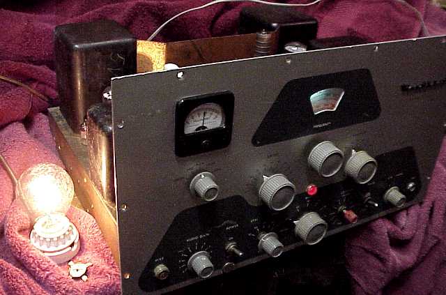
Dummy load lamp is a 116 watt clear-glass traffic signal lamp. The litle device in front of the lamp base is the shorted four-legged loading capacitor.
The Heathkit DX-100 appears in Heath ads from the mid 1950's. Designed for the 160 to 10 meter ham bands (including 11 meters), it sports two 6146 final RF tubes in parallel. A front-panel switch can select several crystal positions or the internal VFO. Modulator output is by push-pull 1625 tubes operating class AB2. The 1625 tube is a 12 volt version of the 807 and is commonly found in World War II era ARC-5 transmitters.
Price of the kit was $189.50 plus shipping for 107 pounds according to the Heathkit ad in the 1956 version of How to Become a Radio Amateur. The ad notes the transmitter is rated "in excess" of 120 watts RF out on CW. AM operation is rated "in excess" of 100 watts. The DX-100 manual rates the output at 100 -125 watts on phone and 120 -140 watts CW. Audio output is 65 watts at 300 to 3000 Hertz. That audio range, which is excellent for normal voice communication, can be extended somewhat by a number of modifications published on the net such as larger audio coupling caps and adding negative feedback. The modulaion transformer has a separate 500 ohm tap. If the B+ connections to the RF output section are cut per the manual, the audio can be connected separately to a 500 ohm external transformer as a 65 watt audio amplifier.
Full Output
Dummy load lamp is a 116 watt clear-glass traffic signal lamp. The litle device in front of the lamp base is the shorted four-legged loading capacitor.
Caution
I have rather limited experience with transmitters so tend to err on the side of caution. A good transmitter can be damaged by improper tuning and testing. Also, high voltage (800 volts DC) is present on top of the chassis at several points. Due care and caution are warranted.
Condition
The front panel of this example sports an extra hole (see hole plug below the power switch) and some scratches. The main chassis top shows considerable rust color. The hamfest (amateur radio swap meet) price was definitely in accord with its poor to fair cosmetic condition and unknown electrical condition.
Initial checks and tests
I vacuumed the cabinet (not shown). It definitely needs to be painted. I cleaned the chassis of the dirt and cobwebs. The bottom of the chassis still shows much original copper color and no rust. Several of the knobs were broken or the wrong type but all of the tubes and components were in place. I checked with an ohmmeter for power line leakage and cleaned most of the accessible switch contacts with deoxit. The line cord is not original. According to the manual, the original plug had two fuses in it, a bit dangerous in some circumstances. However, this example now has no fuses, something I will correct. I checked for continuity of the modulator output transformer and the two power transformers. A previous owner had added a very large 100 ohm resistor to the primary circuit of the high voltage transformer and replaced the hi-volt toggle switch with a three position toggle switch, one position which switches in the resistor. I assume that the modification may have been used to limit power under tune-up conditions and is a good one to leave in.
I next pulled the rectifiers and did a power up by variac to check the power transformers for normal voltages and heating. I used an external supply to reform the electrolytics, especially the two stacked capacitors in the hi-volt plate supply. While in there, I reworked the poor wiring job on the CW/ AM switch and the high volt caps.
More progress.
The outside shaft of each of the dual knob controls had frozen to the front-panel bushings. One of the small red knobs was frozen on its shaft. Some penetrant oil and a bit of time and gentle coaxing solved these problems.
I checked the 25K ohm grid drive control for tracking and continuity since this is a known problem in the DX-100. Also checked the clamp control because it peforms the critical function of cutting off the RF power tubes in the absence of grid drive.
The .02 high voltage cap across the modulator transformer secondary was leaky and was replaced.
I checked every tube with a military TV-7D mutual transconductance tube tester. All passed the tests easily. The 6146B tubes looked to be nearly new. I also checked the meter movement since it is critical to the tests and proper operation.
The VFO is enclosed and very difficult to service. I did not open it, just sprayed some deoxit inside.
More reports as progress is made.
At this stage, I followed the tests in the manual to the letter. The knobs were loosened and reset according to the instructions. I connected a lamp as dummy load. I was able to get 6 ma of grid current easily with either an 80 meter crystal or the VFO. Switching on the plate supply resulted in a glow on the dummy load lamp. Tweaking the controls per the manual instructions resulted in a somewhat brighter glow. The plate meter current stayed below 150 MA. Advancing the coarse load control resulted in the dummy load going out. Shut the unit off. Checked the loading capacitors connected to the control. Found two sections of the octagonal (eight-sided shape) loading capacitor SHORTED. Removed it and carefully wired in 3 transmitting mica caps.
Tested unit again. Dummy load lamp lit up on all settings of the coarse load control. Had suspected the clamp control to be off a bit. Advancing it brought the transmitter to full plate current and lit the dummy load lamp to full brilliance. Switching to AM and injecting hum into the mike jack brought a satisfying amount of modulation current from the meter. DX-100 lives!
Try this link for Heath catalog info on the DX-100.
An RCA Strato-World was the previous item on the bench.