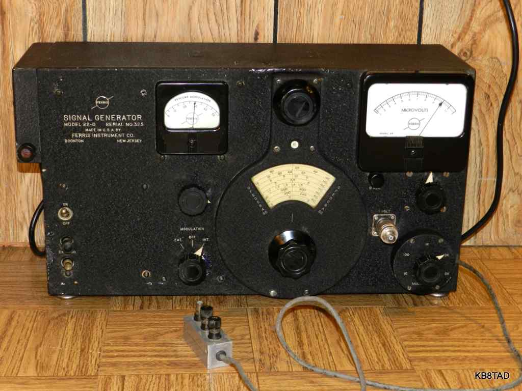
Ferris 22D "Microvolter" signal generator
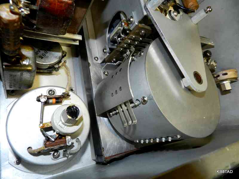
This Ferris 22D signal generator has been sitting on my shelf for quite some time waiting for its turn on the bench. The 22D covers from 85 KHz to 40 MHz in 7 ranges. It has dual outputs. A high level output can be varied from 0.1 to 1 volt RMS into a 30 ohm load. The second output is to a fixed shielded cable with a 30 and a 3 ohm termination inside a small aluminum block fitted with screw teminals on the end of that cable. That output is fed through a precision step attenuator patented by Malcolm Ferris that divides the output down to microvolt levels. In fact, these signal generators were called "Microvolters" because of the calibrated output meter and construction that limited leakage so that microvolt-level signals could actually be relied upon. Each active portion of the generator is double shielded with tube filaments heavily bypassed and a multi-stage filter on the power line input.
The power supply for the unit includes a voltage regulator tube for B+. A type 955 acorn triode is used for the oscillator tube.
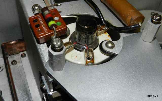
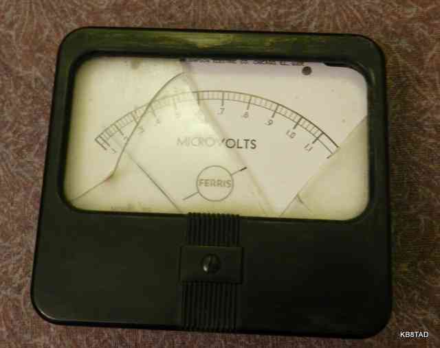
A second 955, wired as a diode, rectifies the high level RF signal for the RF level meter. That meter scale indicates from 1 to 10 microvolts at full scale which corresponds to the 0.1 to 1 volt into 30 ohms of the high level output. The precision attenuator and its resistors divide that high level down proportionately to the microvolt level and the extra physical shielding and electrical filtering limit stray RF.
The original chassis mount high-level output jack had been changed to an "N" type female with a BNC adapter. The original design for the high-level output was to measure stage gain. That output is handy for connection to a frequency counter although for work at the microvolt level, the high output jack should be closed and completely shielded so as to limit RF leakage. I doubt that many frequency counters have adequate RF shielding so as not to compromise the accuracy of the low level microvolt output. Therefore for very low level microvolt work, the frequency should be checked and then the counter disconnected and the port covered.
Schematic
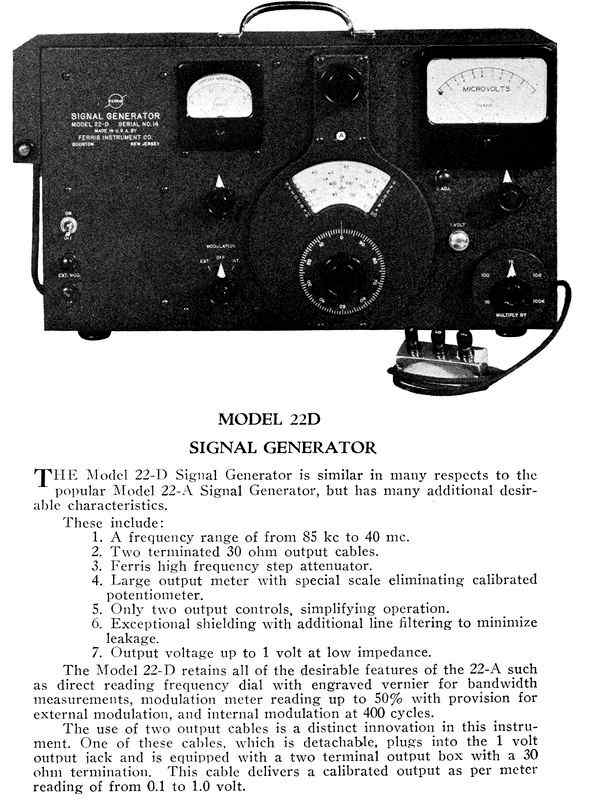
Alan D. provided a couple of pages from a Ferris catalog (above) which nicely describe the device. I recently (2015) located a copy of the schematic dated 1946. Write an e-mail to my address on the homepage if you need a copy of that schematic and the instruction sheet for the 22D.
I was also able to find a copy of the schematic for another Ferris signal generator, model 18B at this link The 18B schematic is similar to the 22D except for modulation metering which the 18B does not have.
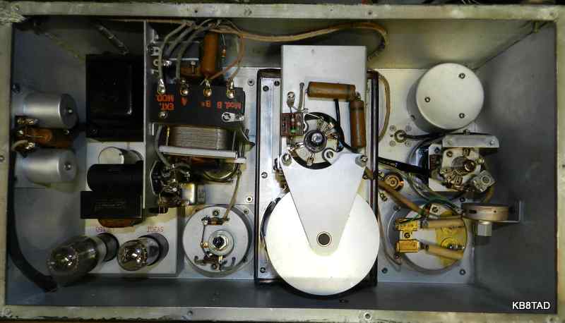
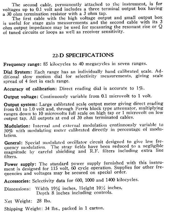
Once opened, the build quality of the Ferris with its all-aluminum case and large copper shield is superb especially the turret band switch which is a thing of engineering beauty.
Repairs
I checked the fuse for proper size and the two sets of line filters for any hazards. I replaced the 0.1 MFD capacitors in the internal filter and the worn line cord with a new shielded 3 wire grounded cord.
Most of the large wax capacitors inside the unit were bypass filters for the 6.3 VAC filament line. I decided that because of the low voltage and impedance, those caps did not really need replacing.
The electrolytic reformed readily on slow power-up. The voltage regulator tube glowed nicely with a line input of about 100 volts or more. Checking the RF output with the scope showed a very clean sine wave. The dial accuracy was almost spot-on relative to the frequency counter reading. The scope confirmed that the high level output was easily capable of 1 volt output.
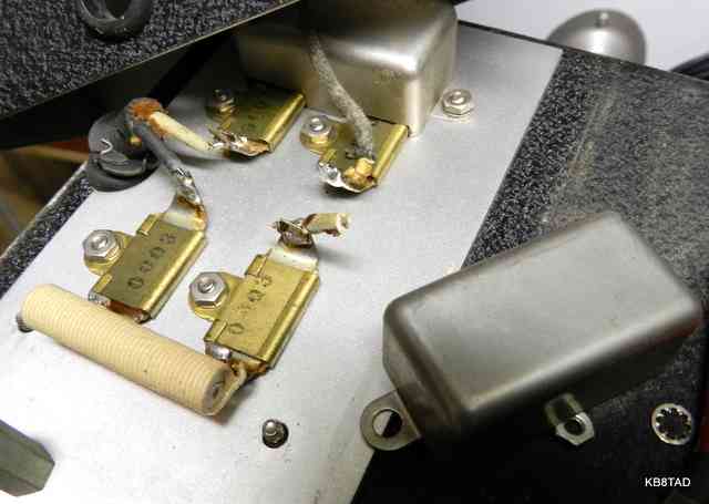
Replacing the RF meter
I had removed the original RF meter because of broken glass but the meter movement was also open. The movement was a Simpson type 29 dated October 1945.
The overstuffed "boxe de junque" yielded a good type 29 meter, but the sensitivity was not the same as the original. I swapped meter movements and changed series resistors so that the replacement would read accurately. I also added back to back silicon diodes across the meter to prevent burnouts. The 955 acorn tube used as meter diode proved to be very weak. I replaced it with a new one. After modification, the meter tracked well with the RF voltage as displayed on the scope.
Modulation meter
The modulation meter turned out to be open as well. I found a matching meter movement but again had to modify the series resistors as well as replace the meter rectifier. The oscilloscope was again used for calibrating the meter which has a full-scale indication of 50% modulation.
Repairs were followed by a thorough cleaning of the black-wrinkle cabinet.
Tripping the bench GFCI
Because of the capacitors in the excellent power line filters in the Ferris 22D, directly plugging it into a GFCI protected outlet causes it to trip with the grounded three-wire power cord. That was expected. All the testing for the 22D with the new grounded 3-wire cord was done using my isolation-transformer and variac combination. However, the grounded power cord should be a standard replacement on any of these sets. Just run them from a standard, non-GFCI outlet.
Using the set with the original 2 wire power cord and power line filters causes about a 60 volt gradient from the chassis to any grounded device at enough current to trip a GFCI but the capacitors causing that voltage are needed for RF filtering.
Performance
Ferris signal generators were considered to be about the best lab-quality microvolters in the 1930s. I was not disappointed by the performance of this one. Cheaper RF signal generators are known for a waveform that isn't necessarily a clean sine wave. This one is very clean. The excellent step attenuator and meter indication on the variable level control makes it useful even today. I will use it as a relatively predictable RF microvolt source. The accurate dial and ability to directly connect a frequency counter make it very useful.
Despite the extensive shielding, the 22D still has some low-level RF leakage with the need to keep some distance between the generator and a receiver under test. I will look at limiting that leakage.
However, leakage is not as bad as my solid state Viz WR-50C which I use as my daily driver. With the Viz, I can almost align the higher bands on sensitive boatanchors with the RF cable completely removed. The Viz leakage is probably just a microvolt or less. I use its leakage as a good indicator of boatanchor receiver sensitivity on the highest shortwave bands.
External modulation
The Ferris does not amplify the external modulation input. On testing using a Hewlett Packard audio generator, it required about 28 volts of signal to provide a 25% modulation level. It is therefore not a good candidate for part-15 AM broadcaster.
About the Ferris Instruments company in Boonton, New Jersey
Malcolm Ferris was granted a patent in 1931 for a "Method and Means for Determining Sensitivity". He filed in August 1937 for his "resistive attenuator", patent 2131101. It was granted in September 1938. Unfortunately, Ferris died in December 1937 accoring to Alan Douglas in his book, TubeTesters and Classic Electronic Test Gear. Ferris' widow hired a cost-cutting manager who apparently fired the top engineers who then in 1939 formed the Measurements Corporation, also of Boonton, N.J.. The Vice-President and Chief Engineer of Measurements was Jerry B. Minter who at the age of 23 had worked for Ferris from 1936 developing a signal generator, a radio-noise and field strength meter, and several other projects. In the late 1940s, Minter was Chairman of the North Jersey section of the Institute for Radio Engineers, now IEEE. See Proceedings of the IRE 1948, page 113 for more information.
Firing engineers, especially as a group, was not a smart move. Eliminating R&D is a quick way to stop a technology company's growth, eventually causing its demise. That was the lesson learned too late by Ferris Instruments.
A list of some other signal generators that have visited the bench can be found at this link.
Date 3-11-13, update 8-12-15
A BC-348Q receiver with Hallicrafters-made Navy power supply was the previous item on the bench.