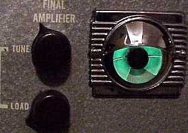
Yes, I love the look of green tuning eyes.
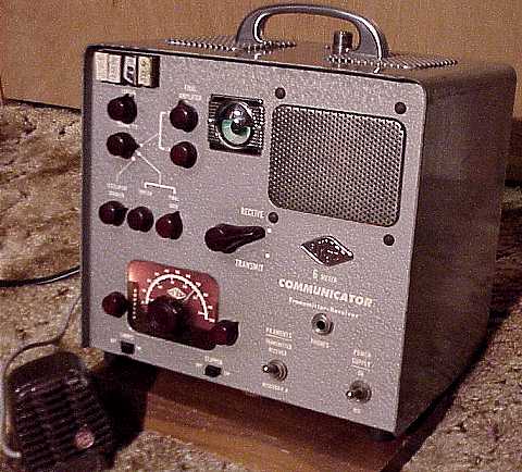
This version, the Communicator II, is much the same as the original but allows for switch selection from among four crystals and has knobs where the original just had screwdriver-adjustable slots for peaking the transmitter. It was priced at $229.95 in 1954. Four generations of the Communicator were produced. The III had a similar shape as the earlier versions but replaced the tuning eye with a meter. The IV changed the physical design to a low-profile model.
Repair progress
I started with a thorough cleaning inside and out with white waterless hand cleaner. I sprayed deoxit on all accessible switch contacts and tube sockets after pulling the transmitter and receiver chassis.
I also pulled the power supply chassis from the set and checked it thoroughly. I did not have a power cord for the set so proceeeded carefully to disconnect wires from 12 pin male Jones power input connector so that no exposure to high voltage AC was possible. The Communicator uses a 12 pin Jones male plug on the chassis. Two of the pins are intended for AC power input. The other pins are used for 6 or 12 volt battery input. Some of those pins are jumpered when AC power is used. The modifications are easily reversible for when I obtain a proper 12 pin Jones female connector. I reformed the electrolytic caps using an external power source.
The set's power supply uses a pair of 12X4 rectifers and provides 12 volts for filament. The set was marked for 6 volts but had apparently been modified for 12 volt filaments to the receiver and transmitter. I verified the use of 12 volts on the filament line by using an outboard low voltage supply first at 6 volts to determine current draw and later 12 volts after being convinced that 12 volts was appropriate. Schematics show that either 6 or 12 volts may be used for filaments if the proper connections are made.
A Sprague "black beauty" capacitor (now often called "black ugly" because of frequent failure) had split its shell lengthwise in the receiver chassis. I replaced it with a modern cap.
After a slow power up with the switch in receive position and connecting a quarter wave piece of wire for antenna, the set began to show signs of life.
The tuning eye is useful for tuning up each section of the transmitter. A switch selects among the oscillator doubler, the tripler and the final drive. The tuning eye is used in each case to maximize the adjustments. The doubler and tripler multiply the crystal frequency by a factor of 6. For example, an 8.4 MHz crystal is used for output at 50.4 MHz.
I used a vintage dynamic microphone for audio. This Gonset does not allow for push-to-talk. It can accommodate either a carbon or dynamic mike but the phone plug must be triple conductor such as is used for stereo headphones. The dynamic mike connections are to the phone plug barrel for shield / ground but the other connection is to the ring, not the tip, of the plug. You can test the mike and the audio amp by using the P.A. function. An external speaker can be plugged in to the phono jack on the back of the rig and the function switch set to P.A.
Our local ham radio club has a weekly net on 6 meter AM with the majority using vintage tube rigs. I was able to join them with this nearly 50 year old Communicator. The rig still needs some tweaks and probable alignment because its performance on receive is weak, but the transmitter is performing adequately at its rated RF output. The manual suggests using six type #47 pilot lamps in parallel for a dummy load. That adds up to 0.9 amps at 6 volts. Instead of that, I just used a single 12 volt half amp automotive light bulb.
Follow-up
A weak 6BQ7A RF amp tube was replaced and the alignment was touched up, but much of the weak receive level turned out to be caused by a problem in the squelch circuit. After repairs including replacement of the caps in that circuit, the volume and sensitivity were definitely up to expectations for this well-crafted 6 meter transceiver.
The NRI Professional Signal Tracer Model 33 was the previous item on the bench.