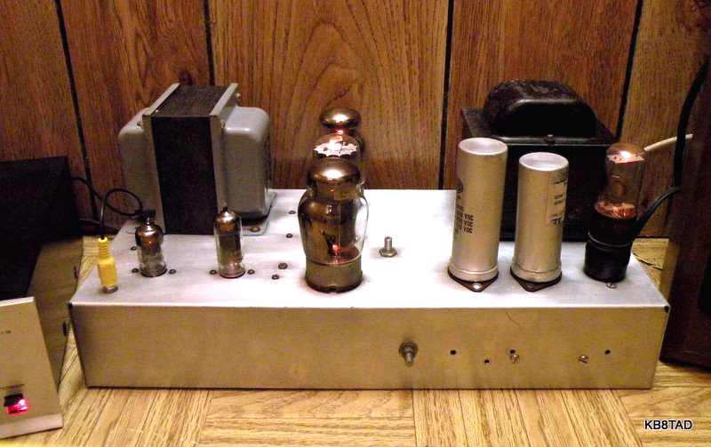
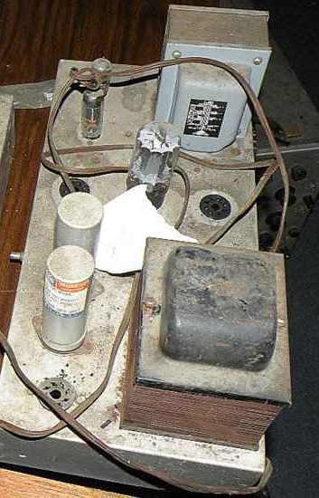
This homebrew amp was purchased at the same auction as the Mullard-circuit homeBrew amp previously on the bench. Like the previous amp, this amp had been gathering dust and dirt for some years but had excellent construction quality and a clean underside. The identity of the missing output tubes was not known when the amp was obtained. The audio output transformer is a Triad S-152A rated from 7 to 50,000 hertz at 65 watts.
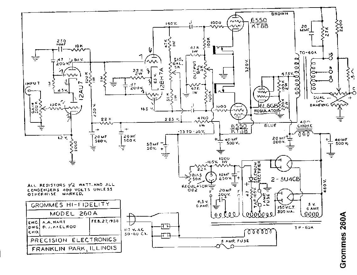
The Grommes 260A schematic is at this link.
The homebrew constructor knew how to build amps. The chassis is only tied to the ground bus at one point. A surgistor was wired into the AC input to ease inrush current.
Early checks and repairs
Like the previous homebrew amp, a thorough scrubbing with waterless hand cleaner made the aluminum chassis look like new again. The power supply filters were reformed and tested with an external power supply (Heath PS-4). A three-wire power cord was installed. After this, a 5U4GB rectifier was inserted and two sets of 4 each C-7 bulbs in series were clipped to the B+ line and ground as a load test.
There are several variations from the Grommes 260A circuit in the homebrew, primarily because the big power transformer that apparently came from a Philco TV did not have a separate bias tap. The constructor used a fixed cap (actually three caps in parallel for 0.06 MFD) from one side of the high voltage winding to a resistor to ground. The bias circuit used a selenium rectifier which I replaced with a 1N4007 diode.
The cathode of the 6L6GB regulator supplies the 320 volts of B+ for the screen grids and the preamp and phase inverter tubes in the Grommes 260A. The Grommes filament line is not grounded to the chassis likely because grounding it would exceed the 6L6GB heater-to-cathode breakdown rating. I found that the power transformer in the homebrew had a separate six volt filament winding which had been left unused. I decided to use that winding for the 6L6GB regulator to alleviate my concerns over heater-cathode breakdown.
I also decided to use that extra filament winding to modify the fixed bias circuit. I mounted a 12 volt transformer under the chassis and wired it to the spare 6 volt winding in reverse fashion to step-up to 65 volts AC which was rectified for fixed bias. The electrolytic caps in the bias circuit were replaced. A divider resistor in series with the bias level pot was changed in value to bring the bias voltage to the proper range. The other pot which is for equalizing the bias for the two output tubes was 25K ohm in the homebrew although the Grommes schematic calls for a 5K ohm pot. While I could adjust the homebrew so that the bias was equal for both tubes, the adjustment was very critical. Just a small movement could vary the voltage too much either way. I experimented with placing resistors in parallel with that pot, settling on a 5600 ohm resistor across the pot which gave me a wider and less-critical adjustment range.
Lots of voltage checks were made before inserting the valuable 6550 output tubes. I checked for voltages at the coupling caps and for the output of the phase inverter. The Grommes 260A schematic lists the expected voltages. In the previous homebrew amp, the grid to ground capacitor in the cathode coupled (long tail) phase inverter proved to be leaky. I was immediately suspicious of the one in this amp which also proved to be leaky and was replaced. Since that cap is in series with a high-value resistor, typically 1 megohm or so, any leakage can degrade the phase inverter function.
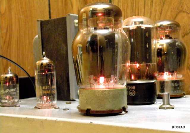
After I was satisfied with the various supply voltages, I inserted a good pair of 6550 output tubes and ramped up the variac, checking voltages under load with proper bias under both signal and no signal conditions. The cathodes of the output tubes in the homebrew have 20 ohm resistors in series to ground. That gave me a convenient point to check for balance for equal output from the tubes. With the earlier change in the series resistor to the fixed voltage adjustment pot, the pot could be adjusted so that its extreme setting was the lowest voltage needed for proper output. Therefore improper adjustment would just increase the bias and could not damage the tubes. I double checked the current draw for each 6550 tube with my Seco HC6 cathode break meter shown with the previous amp.
Changing rectifiers
I did early testing with a 5U4GB rectifier. A GZ-34 /5AR4 would serve the amp a bit better with lower voltage drop and eliminate voltage surges because of its slower warm-up. However, the 5AR4 is rather expensive. I had experimented with combining solid state rectifiers (a pair of 1N4007 silicon diodes) with a TV damper tube to simulate the advantages of a 5AR4. I made an adapter from the base of a dead octal tube and a matching socket. The 1N4007 diodes were wired into the adapter to feed the plate connection of a 6AU4GTA damper. That plug-compatible solution works quite nicely, giving the advantages of the 5AR4 for full wave rectification, slow warm-up, and lower voltage drop at a much lower cost.
Performance
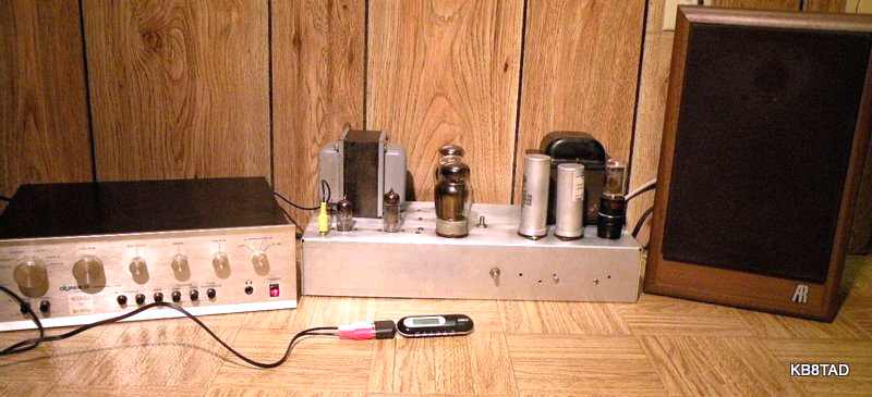
For a very satisfying music test, I connected my MP3 player to the amp via a Dynaco PAT-5 preamp and proceeded to enjoy a variety of music for the next hour or two. The amp performed exceptionally well. The Grommes homebrew can definitely deliver lots of clean power to the most demanding of speakers.
The Triode Electronics website linked above mentions using a 0C3 and dropping resistor as a substitute for the 6L6GB. I will consider that change as the 6L6GB is rather pricey.
Follow-up
Since the issue of heater to cathode breakdown for the regulator tube was no longer a problem with the separate fiIament winding, I looked for optional tubes in the junk box to the expensive 6L6GB. I settled on the 6W6GT which is plug-compatible and can readily handle the current and voltage.
I also decided to change the bias balance potentiometer to one nearly identical to the Grommes schematic specification. I found a larger new-old-stock 6K ohm pot in the junk box, cleaned it with deoxit, and installed it. It provided much smoother control over the grid bias balance.
I determined that that Grommes schematic placed a high voltage electrolytic between the filament center tap and the ground bus because of the possibility of high voltage heater to cathode breakdown. With that breakdown possiblity no longer a problem due to the separate feed for the regulator, I was able to install a more typical hum balance circuit on the main filament line.
11-27-09; follow-up 12-1-09
As noted, the Mullard-circuit Ultralinear HomeBrew Audio Amp was the previous item on the bench.