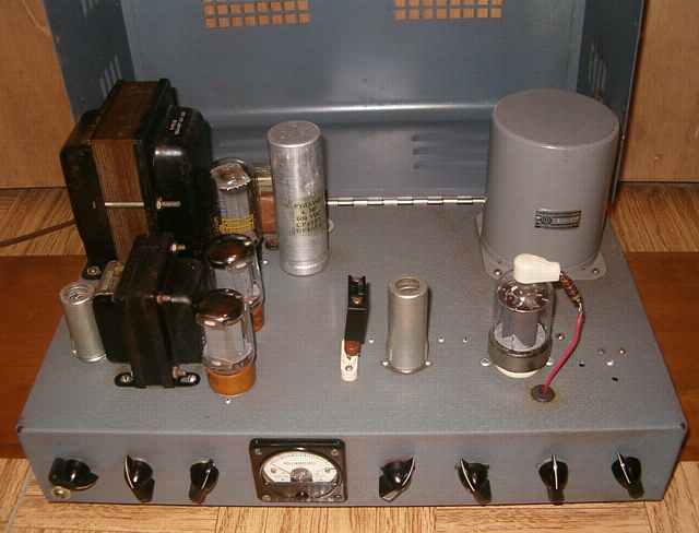
This homebrew transmitter caught my eye a couple of years ago at a hamfest. It appeared to be well made with a nice commercial chassis foundation with a hinged cover and name-brand power, interstage, and modulation transformers as well as power choke. It sports a push-pull pair of Tung-Sol 5881 output tubes (6L6GC equivalents). It has a 12AX7 as speech amplifier and a 6U8 for oscillator and what I later learned was a multiplier. The RF output tube was missing, but I assumed that a 6146 would be an appropriate choice. There were no labels or markings of any kind.
The modulation transformer is a UTC varimatch CVM-1 rated at 30 watts. This led me to believe the RF tube was likely a 6146 as opposed to a 2E26. Both of these have the same pin-out but the 6146 handles greater power. A 30 watt modulator can handle a 60 watt transmitter for plate modulation. The crystal of 8.392 Mhz gave me a clue that this was likely a transmitter intended for 6 meters with tripler and doubler sections to transmit near 50.4 MHz.
7 controls with no labels
The first task was tracing the circuit to determine the function of the seven knobs. The knobs are (from left to right) mike level, off-standby-transmit, meter select (a five position switch with only 2 active positions for measuring grid drive and final cathode current). To the right of the meter, the controls are a variable cap for setting the tripler, a variable cap for adjusting the doubler and grid drive, a variable cap for tuning the final, and a variable cap for loading.
Repairs/ Modifications
One of the difficulties of working on a piece of homebrew gear is not knowing whether it ever worked in the first place. Did the constructor take shortcuts? Was the project abandoned after not working well? One can learn a great deal from a homebrew piece.
As usual, I cleaned the controls and connectors with contact cleaner. I also tried to reform the electrolytic out of circuit, but the 20-20 at 450 volt electrolytic was too leaky to reform. I replaced it with a couple of axial lead 450 volt electrolytics.
The meter had a loose glass window that interfered with pointer movement. I removed the meter from the chassis and opened it. After cleaning the glass and the housing, I used a bit of "Goop" adhesive around the edge of the glass and carefully reassembled to meter. After checking all of the transformer iron with an ohmmeter and connecting a lamp as dummy load, I proceeded to power the unit up slowly with my isolated variac. I limited the voltage to a max of about 100 VAC during early tests. When I switched to transmit, the meter went to full scale reading for RF cathode current. I backed down the variac while adjusting the controls to try to limit the current and only worked for a few seconds at a time. A frequency counter confirmed that the 6U8 was tripling the crystal frequency but there was no indication of doubling and no output. My ignorance and limited experience with transmitters was obvious. I needed more information before proceeding.
ARRL handbook info
At this point, I looked through some old ARRL Handbooks (mid 1960's) to read up on circuits that tripled and doubled. This entire transmitter section had only 2 tubes doing all the work, the dual section 6U8 and the 6146. Locating a schematic for the two tube transmitter circuit. Originally, the closest 2 tuber I found was the 40 watt "Extended Band" mobile transmitter, in the 1965 through 1968 Handbooks, which uses a 6CX8 for oscillator-multiplier and a 12GJ5 for RF out. I later found the actual two tube circuit with the 6U8 and 6146 on which this transmitter appears to have been based. It's the 6 meter version of the "Simple transmitters for 50 and 144 Mc" in the VHF transmitter section of the 1959, 1962 and other ARRL handbooks. The initial article on which the Handbook circuit was based appears in the October 1958 QST magazine.
The writeups for both of the two-tube circuits suggest using a grid dip oscillator to preset the tripler and doubler tuned circuits. I should have thought of that earlier. With my grid dip oscillator accurately preset at the expected frequencies using a counter, I was able to get accurate dips at the link coils with the appropriate variable cap settings.
Having preset the transmitter, I again powered the unit with the variac and found a much reduced cathode current and a slight bit of output on a lamp used as a dummy load. The frequency counter showed the expected six-times-crystal output. Adjusting for resonance and load increased the lamp brightness a bit.
Letting the smoke out
After becoming confident that the transmitter portion was working, I decided to go with full input voltage. The dummy load lit up reasonably well. I switched back to standby. After about half a minute, I heard that sickening "Ssssss" that indicated an electrolytic was cooking. I shut the unit down quickly, but one of the new-old-stock caps I had installed had failed. I had previously reformed and checked the replacements at the full 450 volts with no problems. At this point, I got suspicious. Sure enough, the standby voltage hit the 450 mark well before the full AC line voltage was applied. The builder had underrated the electrolytics. This may have been why his original electrolytic had been damaged as well.
New caps
I replaced the top-mounted cap with a 4 MF 600 volt non-electrolytic for input, wired in a pair of electrolytics in series with equalizing resistors under the chassis, and tested the set again. The voltage at standby hit 540 with just the original 10K bleeder resistor and the new equalizing resistors as load. Under normal modulator and transmitter load, voltage dropped to about 380. No wonder the electrolytics had failed. I began to wonder why the builder had not simply opened the center-tap on standby since that would have avoided the problem of high voltage on the caps. Not knowing if that would affect the transmitter's operating characteristics, I decided to simply go with the series caps and leave the circuit as modified. The extra margin on the replacement and series caps would also allow solid state rectifiers if I later chose that option since the 6146 could easily handle some additional voltage. The power transformer has plenty of headroom.
Modulator repair
Audio input made no variations in the glow from the dummy load. The modulator was not working. The modulator is a relatively simple standard circuit with two triode sections in the 12AX7 as speech preamp and amplifier feeding a larger-than-needed interstage transformer to the grids of the 5881 modulator tubes. Voltage checks revealed several volts of DC on the grid of the second triode section. Replacing the leaky coupling cap solved the problem. Modulation was then obvious with appropriate variations in the glow of the dummy load and a modulated carrier to a nearby receiver. I used an oscilloscope to verify that the modulator could indeed attain 100% modulation when using my microphone.
Overall design
The unit seems to perform as expected. The original designer placed the modulator tubes a bit too close to the interstage transformer with just minimal clearance. Perhaps he originally had a smaller interstage transformer in mind.
I bought this unit at a reasonable price thinking I could simply re-purpose the chassis and the major parts for a transmitter for one of the lower HF bands. That is still a possibility. The 40 watt "Extended Band" transmitter noted above has coil dimensions and directions for changing to any of the 160 through 6 meter bands. Knowing that the transmitter and all of the major components work well helps with future plans. A 160 meter plate-modulated AM transmitter might be fun to build at some later time. Or perhaps an arrangement with plug-in coils for several bands.
The Swan 175 transceiver was the previous item on the bench.