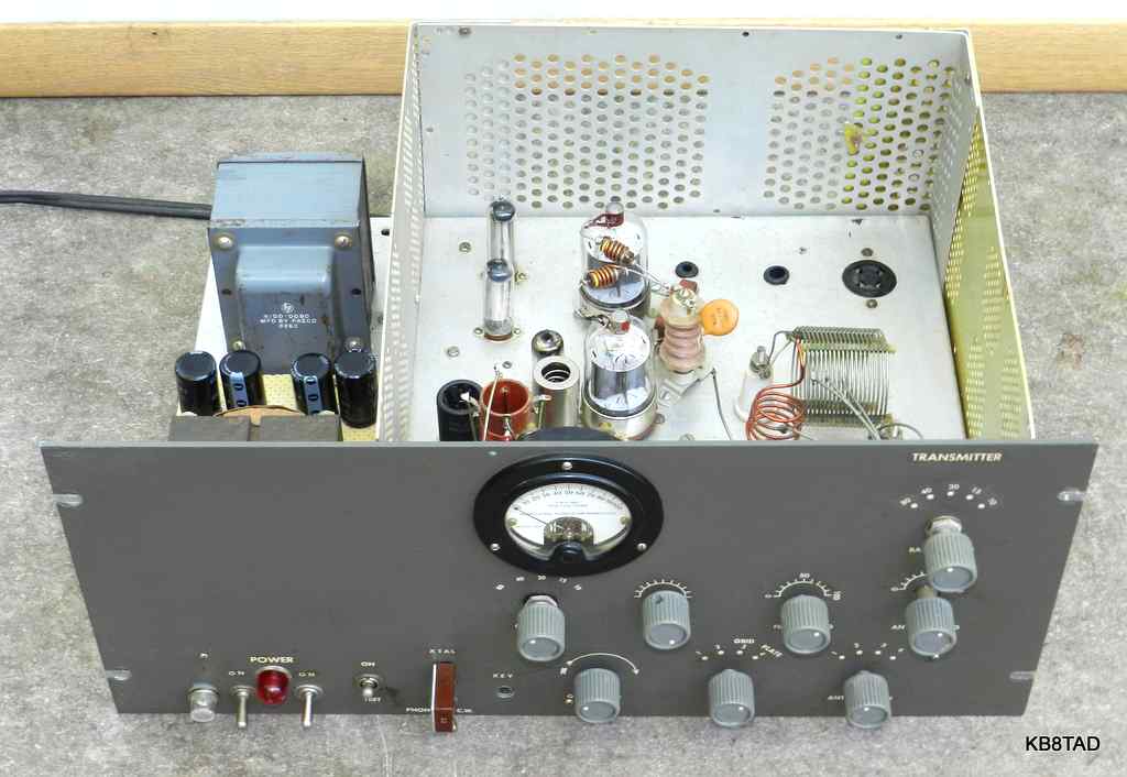
The cane metal top shield for the RF compartment is left off for the moment
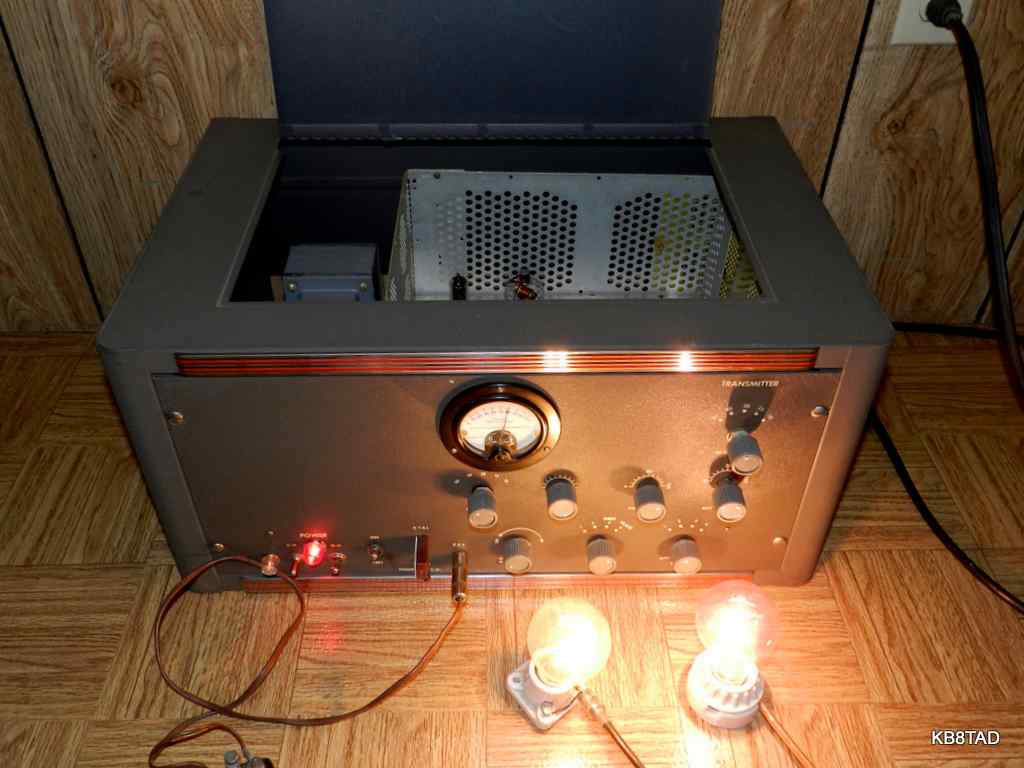
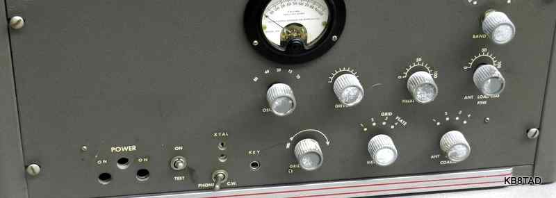
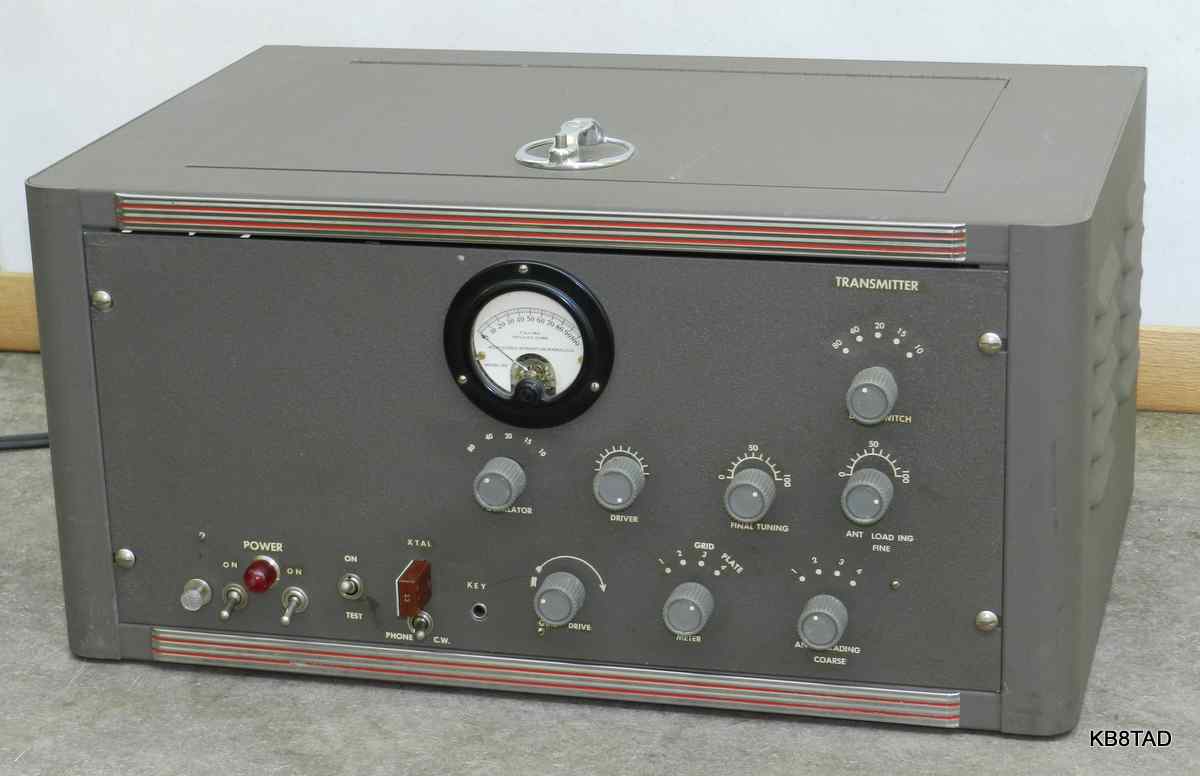
This homebrew transmitter was purchased at a hamfest. I immediately liked the build-quality especially the neat professionally-appearing front panel with matching knobs and decal labels. Also, the rack mount cabinet was in excellent condition.
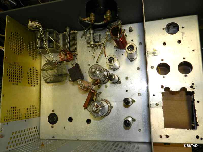
The transmitter was built by K8CUY likely in the mid 1950s. Tube complement includes a 5763 oscillator, another 5763 as tuned driver and two 6146 in parallel for RF output. The set is cathode-keyed and uses a 6AQ5 as screen clamp tube and two 0B2 in series which regulate the oscillator tube screen voltage.
From the extra holes in the chassis and front panel, it was obvious that the set was originally designed for an on-board power supply. It came with a very heavy homebrew outboard supply which I could barely lift. That supply has two power transformers, two chokes, one of which is very heavy, and two tube rectifiers. It was obvious that all that iron could not fit in the chassis space originally designed for the power supply. Because the holes had been cut for an onboard supply and switches, the chassis and the front panel had an unfinished appearance.
The power connector cords for the external supply to the transmitter chassis required male-to-male four pin connectors for the lower level B+ and a length of RG-8 coax with PL-259 connectors for the high level B+. The only ground connection between the two chassis relied on the integrity of the RG-8 braid and PL-259 shells. Any loss of that ground connection would place high voltage between the two chassis. There were also two exposed metal ARC-5 style antenna connectors on the back which were being used as a connection for an external plate modulator. Those exposed connectors carry the full high-level B+. Such connections and cabling were not unusual in the era when this transmitter was built and hams were careful and well aware of the dangers. However, for safety sake, disconnecting the exposed terminals was one of my first acts for the set.
Searching for an article or schematic?
I have not been able to locate an exact article or schematic for the transmitter. Let me know if you recognize it. I decided to sketch out portions of the circuit to understand its operation. The set has a built-in low-pass filter and a safety choke across the antenna feed in case of plate blocking cap failure. I checked the resistors and found the ten watt adjustable chassis-mounted dropping resistor for the voltage regulator circuit was open. The 25 watt power resistor from the plate supply of the 6146 pair to the screen grids was also open. I replaced those. I cleaned and checked all of the controls and especially the drive pot since that is a known trouble spot in similar transmitters. I also checked the meter circuits with a low voltage external supply to properly interpret the grid current and cathode current readings since the meter is simply marked 1 through 10. I found that the grid current indication was based on 10 mA full-scale and the cathode current at 500 mA fullscale.
Rebuilding the transmitter with an onboard power supply
I decided that the original power supply space on the chassis was more than sufficient for a more modern supply using silicon rectifiers and physically smaller electrolytics with larger capacity. No chokes would be needed.
The external supply used two separate power switches for essentially two separate power supplies. I decided to stay with that design. The transformer for the low B+ supply also provides all filament power.
The junk box yielded a transformer that had been part of a tube CB set that would be ideal for the lower B+ supply as well as a Hewlett-Packard Paeco transformer that might work for the high B+ needs. The Paeco produced a no-load high voltage of nearly 1000 volts center tapped. I suspected it was capable of at least 250 mA and probably 300 to 350 mA or more but needed to verify that. I rigged up a load of eight 40 watt 120 volt candelabra bulbs in series to test its ability. The eight lamps would simulate a load of 333 mA at 960 volts. Using a variac, I powered the transformer with the lamp load and noticed that the voltage dropped to 920 under load, about an 8% drop from no load to full load. The lamp load was over 300 watts. That relatively small voltage drop convinced me that the transformer would easily meet the need. As a full-wave center-tapped supply for the high B+, the transmitter would require less than 200 watts at ICAS (intermittent commercial and amateur service). The transformer could easily handle that much at CCS (continuous commercial service).
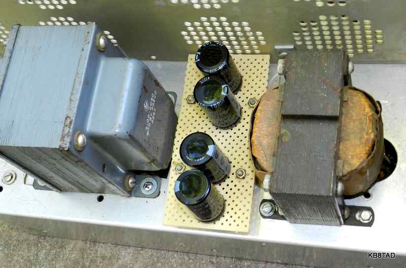
I placed four axial lead 100 MFD 450 volt electrolytics on a piece of perfboard mounted on stand-offs. A long terminal strip provided the space for silicon rectifiers and divider/ bleeder resistors. I also drilled holes for a power cord and a second pilot light, enlarged an existing pilot light hole and repurposed another hole for a fuseholder. The original cutout for a power transformer was rather ragged. I filed that opening to square and smooth the edges. The low B+ supply was wired first and tested. On testing with a 40 meter crystal, I found I could easily tune up for proper grid current and a solid reading when sniffing with my portable frequency counter. I next wired up the high B+ circuitry. I estimated a voltage of about 625 under load using center tapped full wave. I did not use any of the four 6 volt filament windings but did use the 5 volt winding for a red pilot light. For testing, I temporarily connected a separate power cord to a variac so I could power the high B+ side slowly while checking voltages. I put a shorting plug into the open-circuit key jack and connected a dummy load lamp to the antenna connector. The supply worked fine and I was able to tune and light the dummy load lamp. I had the chassis on its side so I could meter the screen voltage.
Letting the smoke out
All of a sudden, smoke curled from the underside the chassis. I quickly shut the transmitter down. Because the set was on its side, I noticed the source of the smoke, a switched-in mica loading capacitor that was rated at 2500 volts. It had broken down despite being in parallel with my low-impedance lamp dummy load. I removed the cap and verified on my cap tester that the mica was indeed very leaky. The junk box yielded a 560 pF ceramic cap that was rated at 6 Kilovolts as a replacement. Since one mica cap was found to be bad, I decide to change out the mica plate capacitor. I had determined to replace it anyway since it only had a 1250 volt rating, a bit light for an RF plate cap. It was replaced with a ceramic cap rated at 3 kilovolts. I completed wiring the high B+ circuitry and tested again. This time no smoke.
Some fireworks
However, I pulled the shorting plug from the key socket to determine what would happen to the screen grid voltage on key-up condition. That started arcing fireworks under the chassis. I shut the unit down again after quickly noting where the arcing was coming from. The metering circuit switch was arcing over and a shielded lead to the key jack was breaking down between the shield and the center conductor.
I puzzled over it for just a minute or two and then determined such high voltage at the key jack could only be caused by full no-load high voltage at the cathode which was only possible if the clamp tube was not doing its job. Sure enough, testing the 6AQ5 found it to be very weak. I replaced the 6AQ5. I also checked the 6146 pair. One was worn but the other was nearly flat. I replaced the 6146 pair with a matched set of used 6293, pulse-rated versions of the 6146 originally intended for use in radar equipment. Those are known as tough tubes with a long service life. I look for those at hamfests. After replacing the tubes and the shielded lead that had broken down, I tested the transmitter again. This time it behaved as expected. I used two 60 watt dummy load bulbs. The transmitter at 300mA easily loaded and lit both bulbs to nearly full brilliance, about 110 watts out.
Future possibilities
The transmitter is already wired for an external VFO. The four pin socket that had been used as an input connector for external low B+ has been left in place for supplying power to an external VFO. The transmitter can also be readily adapted to a final stage that is not keyed. There is room enough to add some more circuitry as may be needed to change the final to class AB amplifier. Connectors for control by an external SSB generator can also be added. A proper connector can also be added for an external AM plate modulator. As a homebrew device, modifications and improvements will not impact value negatively as it might on a commercially-produced transmitter. Experimentation and improvement is part of the enjoyment of ham radio. I had fun completing the transmitter as K8CUY had originally envisioned it.
List of some other transmitters I have worked on
Here is an
index to some of my other transmitter projects.
(See also the Clegg, Conar, Gonset, Knight, Heathkit, Multi-Elmac, Swan, Polytronics, and Hallicrafters categories for more transmitters)
Date 9-4-13
A Bud CPO-120 code practice oscillator from 1939 was the previous item on the bench.