Here's another piece I admit to repairing simply to satisfy my curiosity about the circuit and the function of the device. When these pieces were new, they cost too much to experiment with. Now they can be obtained for just a few dollars. So what can be done with these?
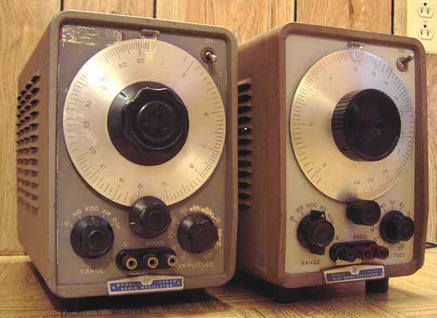
The Hewlett-Packard HP-200CD audio generator will generate sine waves from 5 Hz to a bit over 600 KHz. That puts its upper ranges right into the broadcast band. It uses a balanced version of the famous light-bulb-stabilized wien bridge oscillator developed by -- you guessed it -- William Hewlett who commercialized it with David Packard.
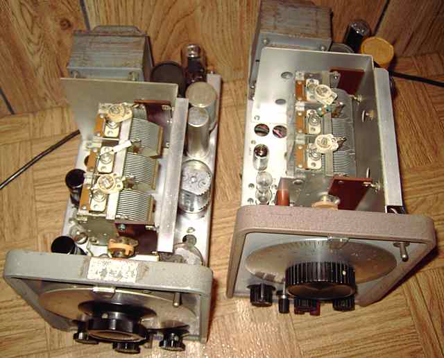
I picked up two HP-200CD, one at a hamfest and one at an auction. They were in two different knob styles and tube variations. Neither one was working. While I have seen the Wien Bridge oscillator in various forms over the years, I decided to repair one or both of these because of the capability of oscillating into the broadcast band. A PDF manual is available from the BAMA site. The circuit shows the bridge for controlling frequency with the familiar light bulb filament in the feedback loop, a pentode voltage amp tube (6SH7 in older set, 6AU6 in newer) and a power amp tube (6AU5 in the older set, 6CW5/EL86 in nice IERC shields in the newer one) as cathode-follower in each side of the balanced circuit.
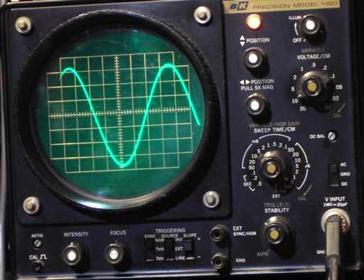
The balanced circuit has positive feedback in criss/cross fashion. The power amps together feed either of two output transformers depending upon frequency range selected. The output transformers feed a bridged "T" constant impedance variable output level control. Output is specified as 10 volts RMS into a 600 ohm load and 20 volts open circuit. At radio frequencies, that makes it a transmitter of about 160 milliwatts. My scope showed a maximum output voltage at nearly 50 times that of my RF signal generator.
Repairs, the older unit,
This was my first time with servicing an HP-200CD. If you have suggestions or shortcuts, let me know. The symptoms for this set were excess current draw and total lack of proper output. As usual, I started with safety checks and then made sure the power supply was functioning properly. I found an open 2000 ohm power resistor and replaced it and the companion resistor with two new matching ones.
Balance needed
On reading the manual, the emphasis was on balance. The cathodes of the 6AU5 power output tubes, shown on the voltage chart as -3.2 volts, have to be within one volt of each other. According to the manual "If more than 1 volt is measured between V2 and V4 cathodes, a bad tube in the oscillator is indicated". Function, stability, and low distortion of output is dependent upon this balance. I found both of the coupling caps (from the 6SH7 plate to the 6AU5 input grid) to be leaky, causing some excess current draw and low cathode voltages. I replaced those. I found that grid emission and variations in the voltage amplifier tubes was a factor in balance and measured the input grid voltages of the 6SH7 tubes, shown on the schematic as the same voltages as the 6AU5 cathodes. Substituting different 6SH7 tubes resulted in considerable variation in grid voltages. I finally found a pair that matched very closely and left well enough alone. My frequency counter showed proper output and stability on all ranges. I was most interested in the top range. A nearby AM radio with signal strength meter confirmed plenty of RF output easily adjustable by the output control.
Repairs, the newer unit
The newer set also showed excessive current draw and some instability in output. The first electrolytic did not reform readily and required replacement. The coupling caps were fine. After replacing the electrolytic, the 6CW5 cathodes were in the proper range but a bit more than 1 volt difference. Swapping the 6AU6 tube positions, as suggested in the manual, did not solve the problem. I found several 6AU6 tubes in the junk box, all from the same manufacturer (Sylvania). Inserting two of those resulted in near perfect balance. I tweaked R-11, the voltage control in the bridge which sets the maximum, to the proper output voltage. The frequency fine-adjustments were close enough that I did not change them. Since I use a frequency counter for monitoring output, I pay little attention to the dial setting itself.
Component failure while on the bench
I let the newer HP-200CD perform for a time on the bench. All of a sudden, no output. Voltage measurements relative to chassis were weird with high negative voltages at several test points. I scratched my head and pored over the schematic, thinking the wien bridge balance circuit had some imbalance. In the circuit, B- is connected to the chassis through a 10K resistor. I was wrong in assuming the balancing circuit was at fault. The circuit was trying to work, but the high negative voltage was caused by a heavy current draw in the B+ side, causing some normally near-zero-to-chassis voltages to swing to the B- direction. After pulling the 6AU6 oscillator tubes, and in turn the output tubes, I still found the voltage anomaly. I finally traced the problem to a 100 PF mica cap that was breaking down under voltage, eventually turning itself into a 300 ohm resistor. It was connected between a 6CW5 plate and chassis. Replacing it brought the set back to life. I tested its sister cap at its full rated voltage and found it to be fine. It is unusual for a mica cap to fail, but it happens on occasion. Because the failure was to chassis, the power supply did not blow a fuse or draw that much extra current. It merely shifted the floating voltage point at the chassis causing all voltage readings relative to chassis to shift in the negative direction.
"Playing" with an HP-200CD
So what good are these other than testing audio amps or aligning very low frequency IF stages? These units put out sine wave CW up to 600KHz and a bit beyond. Has anyone tried to amplitude modulate one of these? At the very least, I suppose a scheme similar to the means of modulating early RF alternators might work, that being a carbon mike in series with the output to an antenna. Experiment and let me know what scheme you have tried that works.
When new this equipment was expensive. It is now relatively cheap and can be used for some functions not intended by the makers, code practice for example. And demonstrating early amplitude modulation.
A Signal Corps rack-mount audio amplifier/ speaker was the previous item on the bench.