I have repaired a number of HP instruments from the analog tube era. These lab instruments have a build quality that I admire. When new, they cost too much to experiment with. Now that they can be obtained at reasonable prices, I find them fun to use and to experiment with for possible alternate purposes.
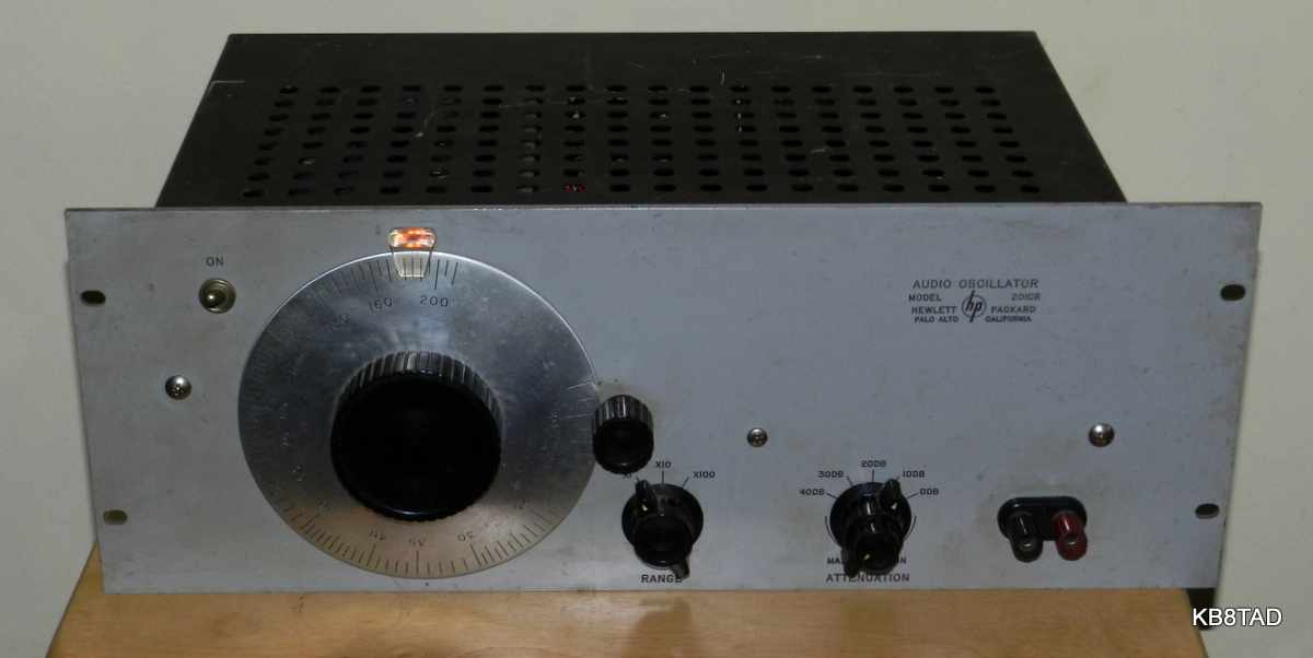
The Hewlett-Packard HP-201CR audio generator will generate sine waves from 20 Hz to 20 KHz. This HP-201CR is serial #006-01509. It is the rack mount version of the HP-201C (hence the "R" after the HP-201C). Price of the HP-201C in the 1956 catalog was $225. The rack mount version would have been more expensive. Its output is three times as powerful as the similar model 200AB at half the distortion. HP lists its primary use as "high quality audio tests". The HP-201C replaced the earlier HP-201B in 1956. The serial number on this piece shows it to be one of the early versions.
Here's the 1956 HP catalog info on the 201C "-hp- 201C, 20 cps to 20 KC, replaces -hp- 201B and offers a superior attenuator with new compact styling at a lower price. Meets requirements for speed, accuracy, ease of operation, waveform purity for high fidelity audio system or component testing, frequency comparison, and transmission line measurements. Delivers at least 3 watts to a 600 ohm load resistor."
A later (1971) PDF manual for the HP-201C is available from the HP Archive site linked on the home page. The manual lists various changes from earlier serial number versions.
Circuitry
The HP-201C combines the classic light-bulb-stabilized Wien bridge oscillator for which Hewlett was granted a patent with a separate push-pull audio amplifier and special output transformer with 600 ohm output. The transformer uses a secondary winding to provide inverse feedback for an excellent flat response from 20 Hz to 20 KHz. The amplitude control (think "volume control") separates the oscillator circuit from the amp circuit. A full shield separates the two sections. The amp section is a typical push-pull amp using two 6K6GT tubes and fed by a split-load phase inverter (one triode of a 6SN7) that is DC coupled from a triode preamp, the other half of the 6SN7. The cathode resistors of the 6K6 output tubes are not bypassed with an electrolytic, thus providing a bit more inverse feedback.
Although the specs call for "at least 3 watts", circuit-wise there is no reason why with very simple modifications, the amp could do at least 3 times that. Like the HP-200AB, the 600 ohms can simply be matched with a 70 volt transformer to speaker output. The amplitude control can then be directly fed with audio for an excellent "monoblock" amp. ("Monoblock" is a relatively recent term for a monaural audio amp without the tone controls or multiple inputs normally provided by a separate preamplifier.)
Repairs
As usual, I started with safety checks, checking for any shorts or low resistance in the B+ circuits and for leakage from the AC power plug to the chassis.
Like most older electronic devices, coupling caps should be replaced. The original ones in this piece were Sprague "Black Beauty", known for leakage. Electrolytic caps should also be checked and/or replaced. Given the build quality of these lab instruments, it was not surprising that little else was needed.
Modifications
I decided to add a closed circuit phone jack to the piece so that it could be alternately used as an audio amplifier when fed with a high level audio input. A matching transformer such as a 70 volt line transformer with about 9 to 1 turns ratio works fine for matching the 600 ohm output with the typical 8 ohm speaker. The closed-circuit phone jack simply breaks the feed to the 6SN7 preamp section. Removing a phone plug from the jack returns the device to normal usage. The "X" in the partial schematic below marks the location of the new audio input modification. The schematic also shows a 6V6GT pair in place of the original 6K6GT pair in my set. HP supplied the HP-210CR with either pair depending upon serial number range.
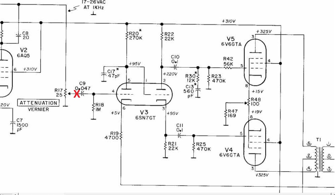
The overall gain of the audio amp is restricted by the large amount of negative feedback. The feedback winding from the output transformer can be disconnected with a switch and the cathode resistor (R19 On the schematic) grounded directly instead of through the feedback winding. That increases gain greatly. I experimented with those changes but decided not to modify the piece further. Let me know what experiments you have tried with these tube-era HP pieces.
List of other HP pieces I have repaired
Here is an
index to my other HP projects.
1-23-16 Re-purposing a Heathkit S-2 Electronic Switch as an Audio Preamp was the previous item on the bench.
Go back to the BA Pix Homepage.