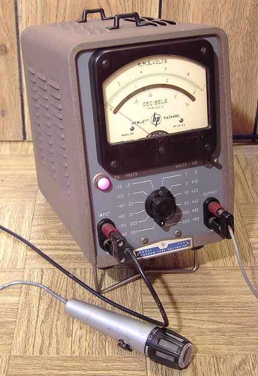
HP-400H getting ready to measure the relative output of a microphone. The output terminals were connected to low impedance headphones for direct monitoring of the sound of the microphone.
I previously repaired several HP-400 models, includingthe HP-400A, the HP-400C, and theHP-400D.
The HP-400H has the largest meter of that group with a 5 inch mirrored scale. All of the 400 series are related. The 400H is essentially a slightly improved 400D. The schematic of the 400H is nearly the same as later serial numbers of the 400D. The specifications are the same for the two although for the 50Hz to 500 KHz range, the 400H is rated at plus/minus 1% of scale accuracy. The 400D does not have a separate specification for that range so the assumption is that its accuracy is 2% for the same range.

Like the 400D, the HP-400H is a wide-band RMS Vacuum Tube VoltMeter with separate terminals for cathode-follower output of its amplifier. It is capable of reading AC from 1 millivolt full scale to 300 volts full scale. The wideband response is from below 10 Hertz to a specified working accuracy limit of 4 Megahertz. The cathode follower output for monitoring, regardless of input switch setting, is specified at 0.15 volts at 50 ohms impedance. Input impedance is 10 MegOhms.
Repairs
A copy of a Hewlett-Packard military manual that applies to both the HP-400D and the HP-400H can be found on BAMA under HP-400D.
This HP-400H needed very little in the way of repair, just deoxit cleaning of its switches and its tube sockets. The coupling caps were in good shape and the meter balance caps fed by the solid state meter diodes had been replaced earlier in its life. I suspect that the coupling caps may also have been replaced. However, it had a very pronounced reaction to thumping of the chassis. That was due to a microphonic tube, the 6CB6 in the V2 position. The microphonic problem was confirmed by listening to the output terminals with an external amp and speaker. I gently rubbed a toothbrush on the various tubes and sockets and not surprisingly, found that V2 caused the most noise with that treatment. It is the second in the total chain of 5 tubes so any microphonics would be amplified by 3 more tubes. I tested several 6CB6 tubes before choosing a replacement.
Working and Playing with it
In addition to microphone testing as shown in the picture above, I listened to the direct output of my ham radio antennas by connecting the coax to the input terminals (using a 200 ohm resistor across the terminals for antennas that had no DC continuity). I then connected a germanium diode in series with the output side to feed an external audio amp. Various shortwave stations could be heard at the same time. Invariably one station would dominate for a time. The meter would follow the signal level like a big S-meter.
A National NC-109 receiver was the previous item on the bench.