
"in a class by itself"
Fisher claimed that its KM-60 "StrataKit" was the most sensitive FM tuner kit in the world. "When it comes to performance, the ultra-sophisticated wide-band Fisher circuitry of the KM-60 puts it in a spectacular class by itself. Its IHFM Standard sensitivity of 1.8 microvolts makes it the world's most sensitive FM tuner kit. Capture ratio is 2.5 db; signal-to-noise ratio 70 db, Enough said."
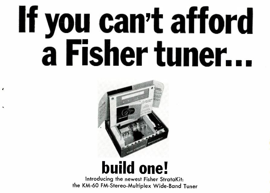
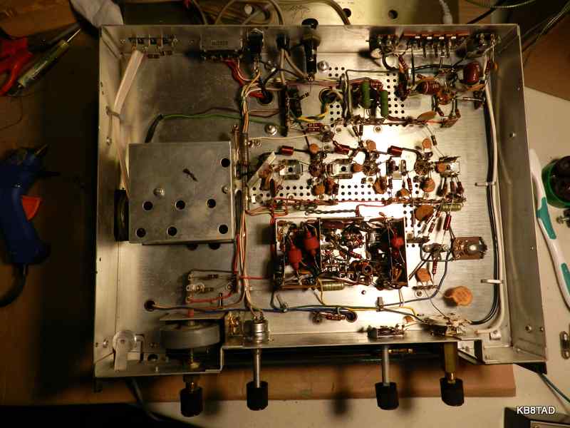
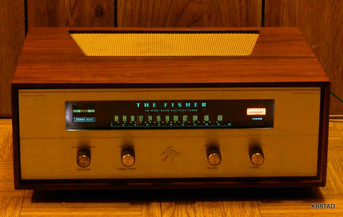
The kit was one of the first with a built-in FM stereo multiplex decoder. The critical multiplex subchassis and the RF front-end were factory built. Priced at $169.50 plus $24.95 for an optional walnut or mahogany case, the kit uses 11 tubes including an ECC88/6DJ8 and ECC85/6AQ8 in the front end, an EM84A/6FG6 eye tube, 4 each 6AU6 for IF and limiter/ratio-detector, 2 each 12AX7 and 2 each 12AT7 for multiplex decoder and audio. A meter measures signal strength and is used as an alignment indicator. The magic-eye tube, called a "Stereo Beam", indicates the presence of a multiplex stereo signal.
Repairs
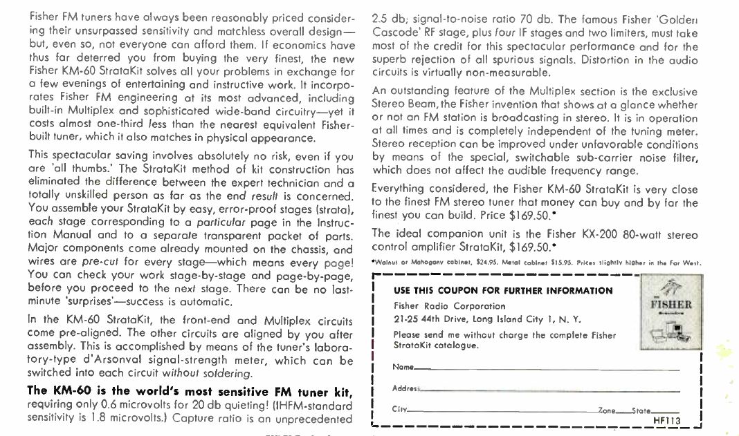
Since kits can vary greatly in quality, I first checked every solder joint. The overall build-quality of this kit was excellent. That may have been partly due to the care that Fisher gave to the design of their kit, but the kit builder did a fine job. As purchased, this set had a broken dial string, an open power switch, and all three pilot lights burned out. The switch was rescued with an application of deoxit.
The line-to-chassis resistor
Un-powered tests with a VOM meter showed some leakage from the line cord to chassis. At first I thought that the line capacitor must be leaky. However, I found that the circuit incorporates an 820K ohm resistor between one side of the power line and the chassis. That fixed resistor "leakage" is there to provide a direct path for static build-up from the antenna connections thus providing a quick path to ground by way of the power line. I have seen this arrangement on many antenna-connected devices. The resistor or equivalent prevents the breakdown of the power transformer primary to secondary through static discharge. I decided to leave the resistor as designed but polarize the line cord so that the resistor only connects to the neutral side. A three-prong cord can also be used.
Replacing the dial cord
I carefully observed the remnants of the dial cord to determine the proper path for a new cord. As usual, I used a length of 65 pound "Spider-Wire" fishing line, a very tough replacement for dial cord.
The Fisher kit used a bead made of lead through which the dial cord was run at its end. After tightening the cord for proper tension on the dial cord spring, the lead bead could be squeezed with pliers to quickly fix the dial cord tension. I opened the hole in the bead, removed the broken cord and re-used it on the new cord.
Intermittents
Most of the capacitors in the set are ceramic which seldom break down. I slowly powered up the set, carefully checking current draw. The tuner was working although relatively weak in sensitivity. Wiggling the front end tubes kicked up the sensitivity intermittently. I then pulled each tube and, with an artists brush, applied a bit of deoxit to each tube pin and socket. That solved the intermittent contact problem, resulting in higher sensitivity.
Alignment
The sensitivity was still not up to its advertisement however. Fisher provided a simplified alignment using the onboard tuning sensitivity meter. I found I could easily tweak the IF transformers and limiter using Fisher's instructions. The dial calibration was somewhat off the mark. Using a frequency counter, I determined that the oscillator adjustment was about 10.9 MHz higher than the tuned stations. I re-aligned the oscillator to the proper 10.7 MHz difference. Tweaking the RF amp adjustments resulted in significant improvement in sensitivity to the level I had been expecting.
Dial lights
I replaced the meter pilot light with the proper type #47 bulb, but the dial scale lights were of the snap-in cartridge style for which I did not have spares. I opted to replace those with a pair of LEDs, an easily reversible but long-lasting solution for tuning scale lighting.
Enjoying it
After repairs and a thorough cleaning including both sides of the dial glass, I relaxed to an enjoyable time of listening to the oldies on a local low-power FM station and watching the Fisher "Stereo Beam" magic-eye tube multiplex indicator as I tuned across the dial.
Manual sources
A partial manual for the Fisher KM-60 can be found at this link.
Here is a
partial Service Manual including alignment information.
More audio equipment
I have repaired a number of other pieces of audio equipment.
A list and links to those devices can be found here.
date 9-12-14
A National NC-183 receiver was the previous item "on the bench".