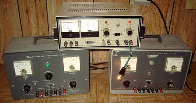
A variable regulated power supply is always useful for testing and repairing boatanchors. While I normally use a Heathkit which is a lot smaller and lighter (pictured below), occasionally a more powerful unit is needed.
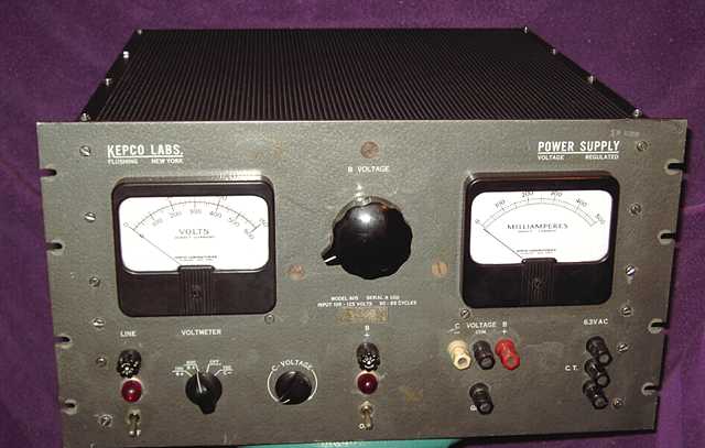
This Kepco 605 heavy-duty high voltage regulated power supply weighs in at over 80 pounds. I "picked it up" (very carefully) at a hamfest (ham radio swap meet). It had apparently not been used in years. The Kepco uses three parallel 6336A dual triode pass tubes fed by three parallel 5R4GY rectifier tubes. To ease the requirement of regulating up to half an amp at the lower voltage points with a top end of 600 volts DC, the main transformer supplying the regulated B+ is controlled by a variac. The variac shaft has an insulated coupling to a flexible shaft that turns a potentiometer voltage control enabling a single control for regulated voltage from zero to 600.
In order for a regulated supply to regulate down to zero volts, a separate negative voltage source is needed. That supply uses a single 5U4GB rectifier. The circuit also uses a 6BQ6 and a 5881. A time delay tube and a relay provide a one-minute warm up period before the B+ circuit can be powered. Voltage reference tubes are a 5651 (87 volts) and an 0A2 (150 volts). I assume that the 6U8 provides for voltage control and the three 12AX7 tubes feed the large pass tubes.A 25K ohm potentiometer provides a variable C- bias supply from zero to -150 volts. The voltmeter can be switched to show 150 or 600 volts. The current meter (on the right) goes to 500 mA full scale.
Note that all of these power supplies use lethal voltages. Do not attempt to service any unless you have the requisite skills and knowledge. A healthy respect for high voltage is a necessary attitude for this or any vacuum tube boatanchor device.
Repairs
The power cord chassis clamp had worn through the outer insulation. I shortened the power cord to repair the problem. The rear 800mA fuse assembly was broken. I replaced it. The power switches and the main fuse showed poor continuity. I used contact cleaner on those to restore function. A general cleaning came next. I pulled the rectifiers and pass tubes to check the power transformers and variac for proper voltages. I then did a slow power up with the on-board variac set at minimum. After a minute wait, the relay clicked on. I could advance the voltage control readily from zero to 600 volts.
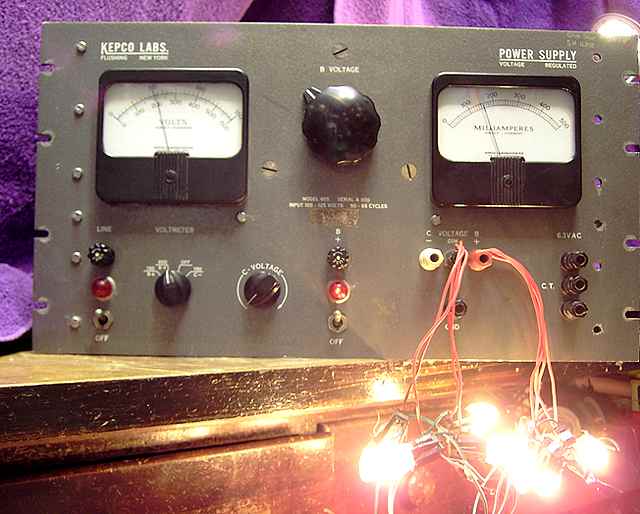
I followed up with a light-bulb load consisting of pairs of C-7 Christmas lights cut from a Christmas light string. The C-7 bulbs are also sold as night lights. Each pair of C-7's can readily handle up to 300 volts at 50mA without undue stress. I used four such pairs for a load test.As expected, the power supply easily handled the load. However the milliammeter movement was impaired and would not always return to zero. I had to remove the entire right side of the case to pull the meter. Not all meter repairs are successful, but I was able to use small strips of masking tape on a thin plastic tool to remove the small bits of debris that were interfering with the meter movement. The large size of the meter helped. I also found that the wirewound bias supply potentiometer was open near its terminal on the low side. I did not have a spare pot. I cut a small triangle wedge of metal from a tin can lid and carefully forced it behind the wires of the wirewound potentiometer near the terminal where the break had occurred. Folding over the very tight wedge completed the repair.
I followed up with a load test consisting of two pairs of 25 watt candelabra lamps. The power supply easily delivered 450 mA at 250 volts. None of the tubes showed any obvious signs of over-heating such as coloration of the plates.
I do not have a schematic for this power supply. If you have one please let me know. I had read that it is capable of delivering 500 mA continuous. My load tests confirm that. By the size of the transformer wire, I assume that the 6.3 VAC filament supply can handle at least 10 amps. Let me know if you can verify. The filtered unregulated high voltage output of the three 5R4GY rectifiers (fed by the transformer and variac) ranges from 232 Volts to 900 volts depending upon variac setting, a useful source if a higher unregulated voltage is needed.
The Heathkit regulated power supplies
I do most of my testing with much smaller Heathkit regulated power supplies. The early PS-4 is nearly identical to the later Heath IP-32 and is similar to the low-profile printed-circuit Heath IP-17 and IP-2717. All are handy units that use a pair of 6L6 tubes as pass tubes for a load of 100 mA continuous and voltages from zero to 400. All except the IP-2717 use voltage regulator tubes and a 6X4 for the negative voltage source. The IP-2717, as the last generation, substitutes zeners and silicon diodes for those tubes. The schematics for all are similar.
The Swan 250 SSB/AM 6 Meter Transceiver was the previous item on the bench.