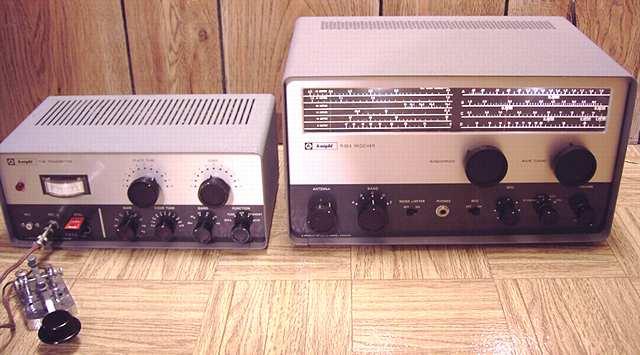
Knight T-60 (left) with companion R-55 receiver (right)
The Knightkit T-60 is a kit-built CW and AM transmitter introduced in 1962-63. A very compact design, it replaced the T-50. Designed for the 80 to 6 meter ham bands, the T-60 uses a 6DQ6B final RF tube. Power input was advertised at "60 watts CW/ peak AM on 80-10. Less on 6". Output is about 40 watts on the lower bands. Output of the final is straight through for 80-10 and doubling for 6 meters. Oscillator/ buffer is a 6FH8. It also uses a 12AX7 for speech amplifier and 6DR7 for audio driver/ controlled-carrier AM modulator.
The T-60 does not have the usual plate or grid current meter. Instead it has a simple two-level RF output meter for tune-up and relative power output. Either a crystal or external VFO can be plugged into the front panel. Price of the T-60 was $49.95 in 1963. The price had increased to $59.95 by 1967.
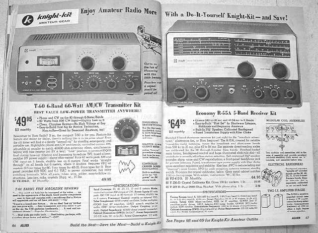
The Knight R-55A is a matching receiver. Allied advertised the T-60 with the R-55A receiver in its 1963 to 1967 catalogs. Compare the size of the very compact T-60 to the much larger R-55A. The R-55A ranged in price from $59.95 in 1963 to $64.95 in following years. Prices dropped in the Spring 1967 sale catalog to $46.70 for the T-60 and $54.95 for the R-55A. I assume they were closed out shortly afterwards.
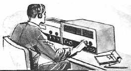
This graphic was captioned:
"A perfect 'First' Station." (The R-55A is the) "Ideal match for the T-60 transmitter on facing page. R-55A has six calibrated scales for the 80 through 6 meter Amateur bands. Graymetal cabinet matches T-60 Transmitter kit styling."
Testing
I reviewed the schematic and did the usual safety checks, making sure the fuse was the proper size, checking for any power line to chassis leakage, and checking for sufficient resistance in the B+ line. The switches and mike gain control were cleaned with contact cleaner and checked for function. My overall impression was that this was a rather well-designed and compact little rig.
I used a variac to slowly ramp up the voltages to reform the electrolytics. The voltages on each of the two capacitors that form the doubler were monitored during the ramp-up to assure they were equal.
Repairs
I used a grid dip meter to confirm that the rig was capable of resonance on each of the ham bands.
I then installed a 40 meter crystal and preset the transmitter controls to that frequency using the dip meter. A 40 watt lamp was connected as a dummy load. I powered the set in tune-up but had no indication on the RF meter. My portable frequency counter showed no indication of RF when held near the oscillator/ buffer tube with the shield removed. Swapping tubes did not change the symptoms.
I shut the unit down and checked all of the connections to the oscillator. The problem was found very quickly. The closed-circuit phone jack for the code key was open circuit. Reminded myself to never overlook the simple when troubleshooting. Cleaning the jack and some mechanical adjustment solved the problem. Of course, plugging in a key would also have solved the problem.
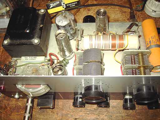
After the key jack was properly grounded, the dummy load lamp lit properly although both the 40 and 80 meter settings required the full antenna loading capacitance and appeared to need even more antenna loading than was possible on 80 meters. At this point I got suspicious. A quick glance at the chassis confirmed that suspicion. I should have spotted it earlier. With a kit, you never quite know whether it was built properly. See if you can spot the problem by looking at the following pictures of the chassis as tested and as repaired.
Knight T-60 with problem
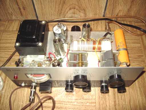
problem solved
The transmitter would have had difficulty loading properly on 80 meters and possibly 40. I'm surprised that the narrow spacing of the loading cap could handle the relatively high RF voltages on the tuning side but there was no evidence of flashover.
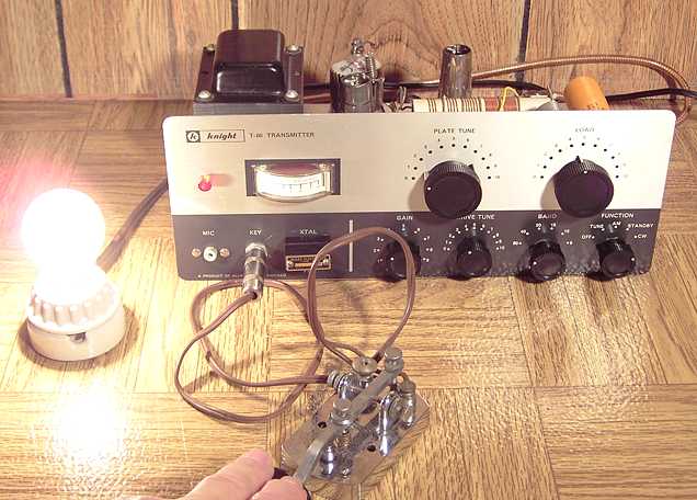
Knight T-60 lighting 40 watt dummy load
T-60 Allied catalog ad opposite companion R-55 receiver.
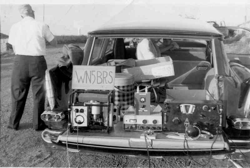
George KX4XK's novice setup with a Knight T-60 and BC-342 as WN5BRS.
Field Day at Lake Altus, Oklahoma circa 1963 with a '58 Plymouth. The right way to tail-gate!