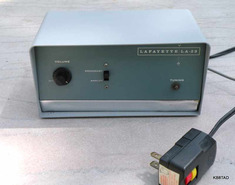
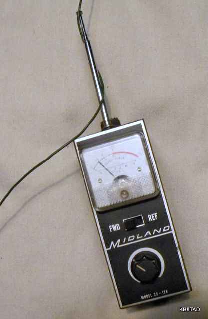
Lafayette LA-23 / KT-195 Amp & Wireless Broadcaster
Wireless AM Broadcasters were enjoyable devices for many experimenters in their youth. Several catalog-order radio distributors carried them as kits. Also known as phono oscillators, a broadcaster enabled a user to broadcast a limited-range signal from a microphone or phonograph to a nearby radio. They are still handy for broadcasting from a CD or MP3 player with a line or earphone level output, sending period music to antique radios.
As a part 15 device, antenna length is limited by FCC rules to ten feet. Experimenters in the past tended to stretch the limits. There are lots of stories on the net of youthful experimenters in the 1950s and 60s boosting both the power and antenna length of their little AM broadcasters.
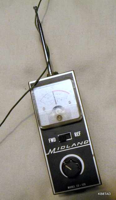
Lafayette LA-23 / KT-195 Broadcaster
As a teenager, I would peruse the ads in the Lafayette, Allied and other electronics catalogs and wonder about the various kit offerings.
I was delighted when offered an LA-23 for just the shipping cost, thanks to Tony DM who had received the piece from Rev. Cliff B, his Navy veteran friend. Rev. Cliff had used the LA-23 primarily as an audio amp as part of an intercom setup, an excellent use. The LA-23 came with a telephone pickup coil so it had apparently also been used to amplify telephone conversations, another good use.
Given its age, the LA-23 had a bit of rust on the metal case. The original paint scheme for the case is a gray color that is essentially the same as the front panel gray but with white paint spattered over the gray. I spray-painted the case in gray primer color with part of the original paint scheme left on the bottom for later reference or matching.
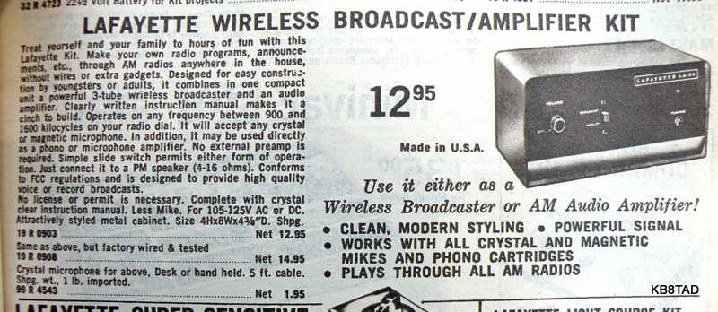
The LA-23 was sold both as factory-wired and as the KT-195 kit. It can be found in the Lafayette catalogs of the 1960's. This ad is from the 1966 catalog. The broadcaster can also be used as an amplifier. Tube complement is a pair of triode-pentode UCL82/50BM8 tubes and a 36AM3B rectifier. The triode sections of the 50BM8 pair are used for audio preamplification with one pentode used for audio output to speaker terminals and the other as a screen-grid modulated broadcaster. A front panel compression trimmer capacitor allows setting the LA-23 to an unused frequency from about 900 KHz to beyond the broadcast band's 1705 KHz upper limit, well into the amateur 160 meter band (not recommended!)
Schematic for the Lafayette Broadcaster
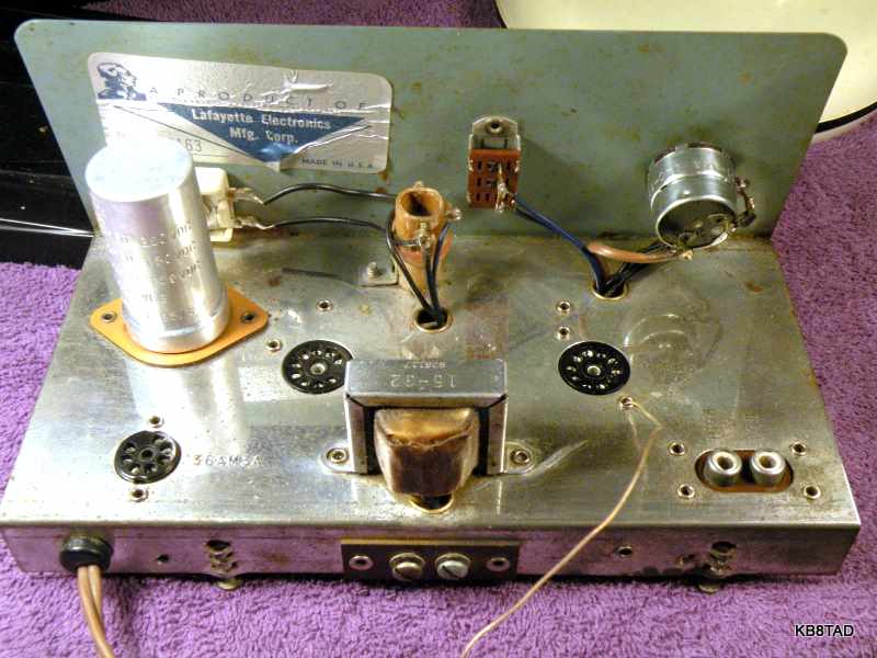
I located a hand drawn schematic of the KT-195 courtesy of Dave A. which is almost identical to what I found except that his schematic shows a double pole power switch. This LA-23 / KT-195 has just a single pole switch. It also has a 0.05 MFD cap from B- to chassis that is not shown on Dave's schematic.
Dangerous circuit
Studying the schematic left me a bit startled by its rather callous disregard for safety. Almost all broadcasters are AC-DC and thus a bit dangerous. However, the Lafayette is even more so. While the chassis has that 0.05 capacitor for floating ground, the exposed electrolytic shell AND THE RCA INPUT JACK SHELLS ARE DIRECTLY CONNECTED TO ONE SIDE OF THE AC LINE. The design actually insulates the jacks from the chassis but directly connects the shells to B-. Why the designers of the Lafayette did something that dangerous is beyond me.
Adding insult to injury is the volume control power switch which switches the line directly to B- and those RCA jacks. That means that the while the power is on, there is a 50-50 chance that the jacks are connected to the neutral side of the power line, seemingly safer. However, when the broadcaster is switched off, the jacks are then live with power from the other side of the line by way of the cold tube filaments. The set is either dangerous when turned off or when turned on depending upon plug orientation.
There is one experience reported on the net by a youthful experimenter in the 1960's blowing out his dad's stereo tape recorder by connecting it to the Lafayette broadcaster.
Making it safer
Experiments with the Lafayette I could improve the efficiency of the wire antenna by placing a ferrite rod "antenna", as found in a typical broadcast radio, just ahead of the 10 feet of wire. I monitored signal strength by placing a passive CB-type SWR and field strength meter close to the 10 feet of wire. Adding the ferrite rod with its high Q coil and distributed capacitance increased the relative signal strength by more than double.
Adding an input transformer I tried a small transformer used for a transistor radio power supply. The turns ratio was about 10 to 1 resulting in an impedance ratio of 100 to 1. That worked very well. Not only did the little transformer provide a proper impedance match but it also isolated the MP3 input from the broadcaster. With the added input transformer, there was now no direct connection to the broadcaster thus further improving safety.
Comparing the Lafayette to the Knight-Kit Wireless Broadcaster
The Knight Broadcaster with its Heising plate-modulation was a not only better circuit but also a bit safer than the Lafayette despite both being AC-DC. It does not have any direct connection of the B- to the input jacks.
Update
According to Bob,
I couldn't help tinkering with the circuit as I would like to have done in
my youth. It never modulated very well. Changing the grid modulation to
something more like the Allied broadcaster make quite a difference.
I experimented with a makeshift PI-Network on the output and did see an
increased output also.
I blew a few fuses as a kid using that thing and yes zapped some equipment
attached to it also.
Like you I felt there is not enough room for a line transformer for safety
and decided to keep the chassis looking as it was.
It has taken a place on my 'yesterdays' shelf along with a few Remco Caravelles, Cub Scout crystal radios, a Remco Tiny Tim radio and other stuff from those by-gone days. Bob, what we learned as kids has served us well. Those experiences? Priceless!
5-1-10; update 10-14-10
The broadcaster needed to be modified to a safer circuit. I thought about a chassis mounted isolation transformer but there was not enough room. I used an outboard isolation transformer but also wanted a safer permanent solution. I decided to replace the power cord with a polarized ALCI (Appliance Leakage Circuit Interrupter) plug repurposed from a hair appliance. The polarized cord was wired with the neutral side now connected directly to B-. The power switch was re-wired. The hot (line) side of the power cord goes to the power switch and the other side of the switch is now connected to the rectifier plate and filament connections.
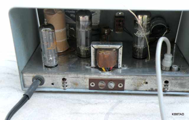
Grounding the RCA jack shells while plugged into a properly-wired outlet will pop the ALCI, shutting off power until it is reset, but will not damage an attached component or result in a shock. An improperly wired outlet will also cause the ALCI to pop when the RCA jack shells are grounded while limiting any shock hazard.
The Lafayette uses ceramic capacitors almost exclusively. I did not have to replace any components. The volume control, the RCA jacks, and tube sockets were cleaned with deoxit. My MP3 player output did not match the high impedance inputs. For early testing, I used an amplifier to raise the level of the MP3 player to provide full modulation. I found I could get good coverage to about a 30 feet radius using the prescribed 10 feet of wire for antenna. The signal could still be heard easily to about 60 feet but dropped off rapidly to the noise floor after that. I measured the RF output at 2.3 volts across a 1000 ohm resistor, yielding an output of about 5.3 milliwatts of RF, well below part 15 limits.
The output level of a my MP3 player did not match the input needs of the broadcaster primarily because of the impedance mismatch. The MP3 has a low impedance output while the broadcaster has a high impedance input.
The competing Allied Radio Knight-Kit broadcaster can be found at this link.
This left me wondering why Lafayette did not copy the better Knight-kit circuit which would not have required any addtional components. In its design, the Lafayette does not use both pentode sections of the 50BM8 while switched as a broadcaster. The screen modulation of an oscillator is also more prone to problems such as a bit of frequency modulation.
If you had a Lafayette LA-23 / KT-195, let me know what experiences you had.
Bob - KA8FVW modified his KT-195 for plate modulation. His website
shows before and after schematics and pictures of the modulation waveforms for the KT-195 after the changes.
I had a KT-195 Lafayette broadcaster in 1963 when I was about 10 years old. I recently found one on Ebay and got it! When I was 10 years old, it was a bit disappointing that my home made one transistor transmitter out performed this great looking kit. So, naturally I had to see what could be done about that being given a second chance at childhood dreams.
Go back to the BA Pix Homepage.