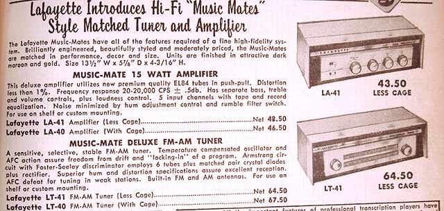
As a teenager and even as pre-teen, I was intrigued by the ads and catalogs from companies such Lafayette radio. So much so, that when I see a piece of Lafayette equipment from the tube era, I am attracted to it and want to find out just how well it was made and how it can perform. That was the case with this Lafayette pair I found at a hamfest (ham radio swap meet). The copy below is part of a 3 page advertisement in the December 1957 issue of Popular Electronics.
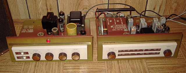
The LA-40 amp uses a pair of 6BQ5 tubes (EL-84) in class AB1 push-pull, a 12AX7 preamp and a 6U8A preamp / phase inverter. Rectifier is an EZ-81.
The LT-40 tuner is covered by Sams Photofacts number 439-7. Its FM tuner section is good for the era but, as expected, not as sensitive as that of a modern high-end FM receiver. However, most modern high-end receivers give little attention to the AM side. The LT-40 will easily outperform modern sets on AM reception with its two stages of IF amplification.
Repairs
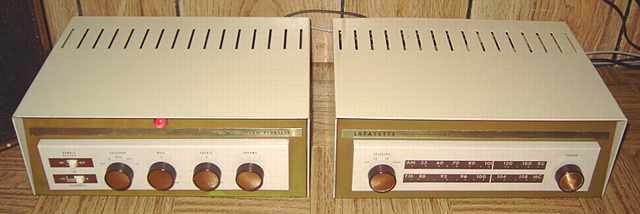
The LT-40 tuner just needed some cleaning of its switches. I was impressed by its AM broadcast performance. It is quite sensitive with its built-in rod antenna. It also has provisions for connecting a larger antenna. When connected to an outdoor antenna, it easily pulled in very weak stations and made for a fun daytime AM broadcast DX experience. The only modification I made was to polarize the power plug so as to assure that the 0.047 capacitor that is attached between the unswitched side of the power line and the chassis was on the neutral side of the line.
Cooling a hot amp
The LA-40 amp needed a lot of help. The on-off switch was intermittent. Contact cleaner cured that. Two sections of the four-section electrolytic had been replaced earlier in its life. I measured the B+ at the replacement cap and found it to be 480 volts with 120 volts AC input. The replacement was tied under the chassis and rated for only 400 volts. I located a NOS (new, old stock) replacement for the multi-section original cap, reformed it separately and installed it. The voltage was still much too high so I kept the variac at about 110 maximum to avoid overvoltage while testing. The filament voltage was correct at about 117 volts input, the amp's design voltage according to the information on the chassis, but the B+ was over the max of the electrolytic at 460 volts. Operating the amp at 117 volts also caused the amp to draw too much current resulting in some excess heating of the power transformer. Bias voltage and the cathode resistor appeared to be correct. Replacing the coupling caps to the EL-84 tubes reduced power draw slightly. However, as expected, the slightly reduced current draw resulted in an increase in B+. And the relatively small power transformer still was getting a bit too warm too quickly. Also, the chassis indicated 50 watts as the power draw at 117 volts input. I thought that possibly the transformer might have been an incorrect replacement but there was no evidence of that.
Modifications
In checking tube manuals for specifications and load line graphs for the 6BQ5 /EL84, the plate voltage is specified at a maximum 300 with the screen at 300. This piece had the plate voltage at 460 with the screens at 277 at 117 volts input. And the power transformer was drawing too much and heating. The power transformer did not show any faults that might have explained the high voltage. None of the resistors and none of the electrolytics were out of specification. I tried another pair of EL-84/ 6BQ5 tubes to see if that was a factor. However, the conclusion remained the same. The voltage was just too high. Whether a design fault of pushing these tubes to the limit or some other fault, I decided to modify the amp before I fried the 50 year old power transformer or killed off the output tubes.
I thought about adding a choke for choke input. Instead, I ended up inserting a resistor from the transformer center tap feed to the chassis (B-). I also added a resistor between the rectifier output and the input electrolytic. After studying the tube load-line charts, I also added some cathode resistance to bring the quiescent bias up to about 13-14 volts. Power draw tests indicated that the bias was still proper for class AB1. I made these changes one at a time and incrementally reduced power draw from 0.67 amps at 117 volts to about 0.47 amps, a figure much closer to the 50 watts figure that the chassis has printed on it. The transformer stills heats up somewhat but not to excess. The output tubes have 400 volts on the plates and 266 on the screens, still somewhat higher than called for in the tube manual but less than original, and the sound from the amp is excellent.
The schematic?
Sams has the Photofact for the tuner but not the amp. I'm looking for the schematic with voltage references on it to see if I may have overlooked something. I first thought that the power transformer was designed for Japan (100 volts AC input ) but the correct filament voltage at 117 VAC input does not support that argument. I looked to see if a choke might have been on the chassis. Absolutely no evidence of that. In hindsight, adding a choke for choke input may have been a good change, but I did not want to drill holes for a modification. If you have a surviving Lafayette LA-40, let me know how hot its power transformer gets and what B+ voltage it is running. Note that there was a later Lafayette amp that also had LA-40 as model number, but that is a different piece. I believe the later LA-40 is a solid state amp.
7189A?
One possiblity for this amp is that the EL-84 tubes in the amp were supposed to have been 7189 or 7189A which are rated to handle higher voltages. If that is true, then I question why the power transformer seems so under rated with a 117 volt AC input at 50 watts. If you know the answer, let me know.
More info
The Sams Photofact for the LT-40 tuner specifies 30 watts as power draw. However, the Sams Photofact also notes a power draw as tested of 0.31 amps at 117 volts which is actually 36 watts. If that same 20% margin was applied to the 50 watt draw of the LA-40, that would mean a draw of 0.51 amps or 60 watts, a more likely power draw for the amp. However, a draw of 0.51 amps is still less than the original 0.67 amps observed.
A Conar Model 230 Signal Tracer was the previous item on the bench.