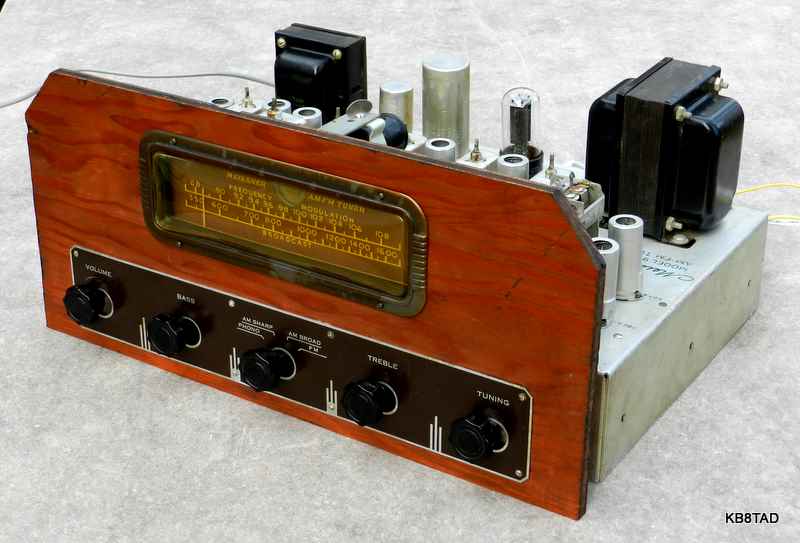
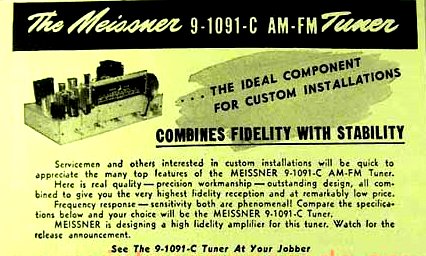
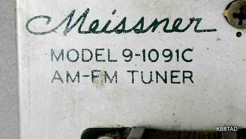
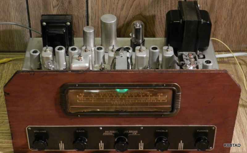
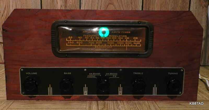
I have always been drawn to Meissner kits and circuits ever since seeing their very descriptive "How to Build" Instruction Manuals. The Meissner 9-1091C AM-FM tuner dates from 1950 and was intended for mounting in a custom console. While Meissner was known for kits, this is one of their more complex offerings and was factory built. Price of the 9-1091 was $245, serious money in 1950.
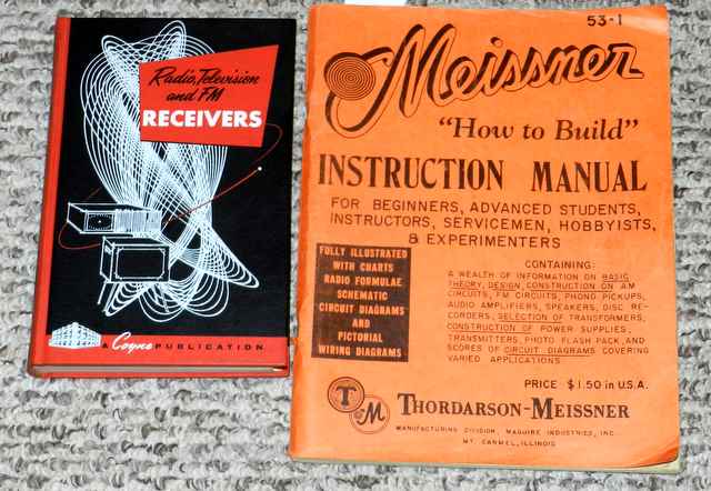
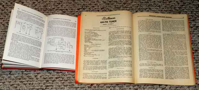
A four page writeup including the schematic can be found in Meissner's 1952 edition of their "How to Build" manual, pages 68 to 71. Meissner published and sold a number of manuals/ catalogs containing schematics and pictorial images of their kits as well as a wealth of information on the circuits. That complete Meissner "How to Build" INSTRUCTION MANUAL can be downloaded as portions via links on the homepage. Click here for the Meissner link. This model can be found in Part 4.
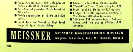
A description can also be found in the 1951 Newark catalog. The tuner is covered in Sams Photofact 116-8 and Rider Volume 19. One interesting feature is that the standard 300 ohm FM antenna connections are also used for AM.
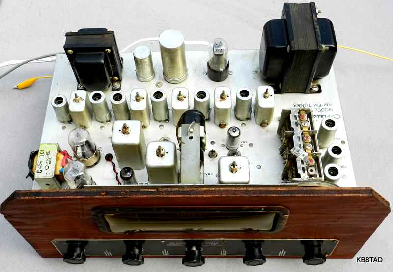
The tuner uses 18 tubes including rectifier and eye tube. The RF and IF amplifier sections are completely separate for AM and FM. The AM section features a 6BA6 tube for RF amplifier, two 6BA6 for IF amp with three IF transformers and a 6AL5 detector. The FM section has a 6BA6 RF amp, 6C4 oscillator, three 6AG5 tubes for the IF amp, two 6AU6 tubes for the limiter function and a 6AL5 discriminator tube. Each section also uses a 6BE6 for converter or mixer.
Repairs on the AM side
This tuner was purchased at a swap meet. The power cord was cut off and the eye tube was missing. It came with a custom plywood panel that included the tuning escutcheon and knob control plate. After replacing the power cord and the eye tube, the set proved to be DOA. However, the electrolytics reformed well. The set was dead because of a defective audio interstage transformer that is used for the 500 ohm output to an external audio amp. After calculating the probable impedance and turns ratio required, I found a suitable substitute in my well-stocked "boxe de junk" that fit without modification.
I first worked on the AM chain, finding a hum in the audio which was caused by heater to cathode leakage in the 6BA6 in the first IF. I replaced it as well as two other 6BA6 tubes which proved to be weak. All the other tubes tested well leadng me to conclude that the FM section had probably seen little use. I also replaced a number of capacitors in critical locations such as the high impedance AVC line, the audio coupling caps and the screen grid caps. Deoxit was applied to the controls. After alignment and repairs, the AM side was every bit as sensitive and selective as I had expected.
Repairs, FM side
The FM side was also dead, although I could hear noise. The RF trimmer cap mounted on top of the main tuning capacitor had one side unsoldered leading to the conclusion that someone else had worked on it. I re-soldered the connection. A quick check with the frequency counter confirmed that the FM oscillator was working but the frequency was about 20 or 30 MHz higher than the expected tuning dial frequency plus the 10.7 MHz of the IF. Tweaking the re-soldered trimmer made no difference. Conclusion, bad trimmer cap. I found and tested a new old stock trimmer cap that was close to the proper 3 to 13 pF range as shown in the schematic. Tweaking it brought the oscillator to the proper range with accuracy on the tuning dial. Several stations could be heard. I also tweaked the RF trimmers.
However the audio was distorted and, in the case of a strong local, tuning could provide peak audio on either side of the proper setting but not at the correct point. The tubes had tested as nearly new. After checking the circuitry carefully including the accuracy and balance of the critical resistors in the discriminator stage, I concluded that the main problem was alignment. The first clue was the inability to directly tune that strong station.
FM alignment
Not having a proper sweep generator, I used the voltage method to align the set as described in several publications including chapter 8B "Alignment of F-M Receivers" in the Coyne book Radio, Television and FM Receivers (volume 2 in the series Applied Practical Radio - Television).
Since the IF chain in this set is not stagger tuned, alignment is similar to an AM radio IF stage with the exception of using an unmodulated 10.7 MHz RF signal and monitoring the limiter grid voltage for gain. I was amazed at how much the grid voltage increased despite my reducing the signal generator output as needed. The adjustment peaks were quite sharp. I followed up with connecting the meter across the two 100 K ohm resistors on the secondary side of the discriminator transformer and adjusting the transformer balance for zero voltage. (Secondary side adjustment screw is under the chassis.) Again, the adjustment was quite sharp. I used a high impedance digital meter since that meter could handle either positive or negative voltage and also read very small voltages. I checked to see if equal voltages positive or negative could be produced by changing the signal gnerator setting up or down an equal amount from 10.7 MHz.
If I were using a sweep generator and scope to do the alignment, I would likely use the voltage method first and just use sweep alignment to double check my work.
Performance
As expected, alignment made a huge difference in sensitivity and the quality of the received FM signal. The Meissner was finally showing what it could do at its sensitivity specification of 10 microvolts. All the local stations as well as more powerful distant stations came in well. The Meissner obviously cannot compete with the FM side of my high-end Marantz or Pioneer receivers of the mid 1970s in sensitivity but was holding its own as a 1950 design. My favorite use for the tuner is for AM broadcast which the Meissner does very well. For FM, it works great at receiving the signal of a small FM modulator/ MP3 player originally intended for use in a car that I use as FM broadcaster for piping music throughout the house.
Links to other Meissner equipment I have had "on the bench"
date; 12-27-11