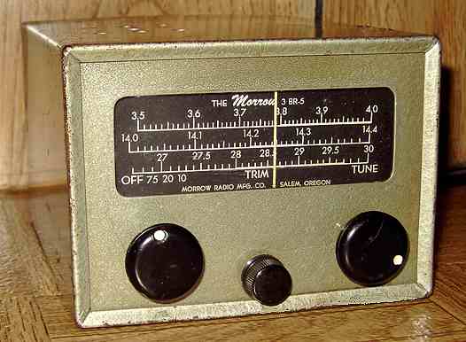
The Morrow 3BR-5 converter covers the 10, 20, and 75 meter ham bands. A 3-gang variable cap tunes the RF amp, mixer, and oscillator. It was designed for mobile ham band reception using an automobile radio as a fixed IF at 1525 KHz. The converter uses a 6AB6 as RF amplifier, a 12AT7 as oscillator, a second 6AB6 as mixer, and a 6AL5 as noise limiter (to reduce impulse car ignition noise). Power requirements are for 200 to 250 Volts B+ at 20 to 25 mA supplied from an external source, typically the car radio itself, and 6 Volts for filament power. The filament supply can be changed to 12 volts if a 12 volt pilot lamp and a 12AL5 are substituted and the remaining filaments jumpered for series connection.
I assume the use of these sets was short-lived since factory radios in many 1957 or newer model year cars stopped using high voltage power supplies, opting instead for special tubes using just 12 volts of B+ and solid state outputs. Later, of course, car radios were completely solid state.
Manual and schematic
The manual for the similar Morrow 5 BR-2 can be downloaded from BAMA. The 5 BR-2 covers more bands. According to the notes on the schematic, "All Morrow converters use the same basic circuit." The 5 BR-2 schematic can be used for the 3 BR-5 as well. The tube layout for the 5 BR-2 specifies a 6CB6 in place of one of the 6BA6 tubes found in the 3 BR-5. Let me know which tube is the correct factory choice for the 3 BR-5. In the circuit, either the 6BA6 or the 6CB6 would be plug compatible.
Repairs
A shielded umbilical cable with four-pin plug supplies power and connects the noise limiter to an automobile radio. The B+ pin of the plug was found to have an intermittent bad solder joint. Another bad solder joint was found in the converter itself, causing intermittent filament power loss for a couple of the tubes.After these repairs and locating a matching jack for the umbilical as well as two matching Motorola antenna plugs for the coaxial input and output connections, the converter was tried with a an external power source and a Realistic (Radio Shack) solid state multi-band portable radio with an S-meter. The radio was chosen because its external antenna jack is a Motorola as found on a typical car radio.
Alignment
The converter was easily aligned using a frequency counter to adjust the oscillator and a signal generator and the S-meter to adjust the RF amp and mixer.
Performance
This is my first experience with a Morrow or similar car radio converter of the vacuum tube era. While the converter seems to work reasonably well, I quickly realized that the little set is limited largely to AM reception. There is no BFO in this or similar converter, thus limiting usefulness to AM. Sensitivity is somewhat difficult to judge since I did not use a mobile antenna with the converter, and reception and selectivity are in part dependent upon the quality and the IF frequency of the companion car radio. (Car radio IFs were often 262 KHz, preferred over 455 KHz for greater selectivity.) The Morrow instruction manual recommends modifying the car radio to add an RF gain control and connections for the noise limiter.
If you used one of these Morrows when it was new, share your experiences.
Just for fun
I also tried the Morrow with a Conar Model 230 TRF signal tracer . It worked surprisingly well but with the expected sacrifice of some selectivity.
A Remco Radiocraft amplified crystal radio was the previous item on the bench.