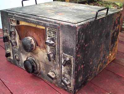
Condition as acquired
National NC-120 / Navy RAO-2
The before picture shows an example of the type of condition some of this heavy metal comes in. This is the National NC-120 which wears a WW II Navy uniform as the RAO. (And this one looked like it went through the war. :-) There are no Navy nomenclature tags on this set, but it has been identified as the RAO-2. This version has the S-meter but no connector for a Panadaptor. Based upon the civilian NC-100XA, the National NC-120 was primarily manufactured for sale to the military. Whether it was ever offered for sale to non-military users is doubtful. It is believed to exist only as the RAO. If your RAO is missing its tags, a common occurrence, see below for hints on identifying an RAO model.
This NC-120 covers 540 KHz through 30 MHz for general coverage in five bands. It and all other NC-100 series sets are sliding coil-tray receivers. The entire bottom section consists of a cast aluminum tray of tuning circuits, each for a different band. The entire tray moves so as to select the proper set of coils for each band. The tray is attached to a rack (a flat piece of metal with teeth to match a gear) which is moved by a small gear (pinion) in the same manner as rack-and-pinion steering for an automobile. The large lower knob moves that pinion. (See also the National NC-200). In designing the sliding coil tray sets, National engineers wanted to avoid the use of bandswitches. The sliding coil tray design gave them the advantages of the HRO-style plug-in coil sets in an all-in-one design. The NC-100/100XA was a compromise since its coil tray design size allowed for only one RF stage. The HRO had two. The NC-120/RAO-2 has two tandem sliding coil trays and two RF stages and more closely emulates the HRO. With obvious superb mechanical and electronic engineering, all of the sliding coil tray sets and especially the NC-120 show their heritage as descendants of the early HRO.
Why did National build the NC-120/ RAO-2 with two RF stages when the NC-100XA only needed one? The Navy wanted a very quiet receiver that could not be detected by an enemy. Maximum radiation had to be less than 400 picowatts. This required an added input tuned RF amplifier in a separately shielded compartment. The separate section helped to prevent RF energy from the receiver oscillator and mixer sections from reaching the antenna and enemy direction finders.
According to NAVSHIPS 900,351-1B and the National RAO-2 manual available for download from BAMA
"The equipment is designed for use at installations where radiation from the high frequency oscillator, located within the Radio Receiver, must be less than 400 micro-micro-watts as measured at the receiver antenna input terminals."
(Thanks to Sherry Guttery of Sherry's Boatanchors for this information.
See also the Scott SLRM for info on another low radiation receiver and the Navy's use of RME preselectors for isolating other radios from antennas.
Both the NC-100XA and the NC-120 have 11 tubes. The NC-120 has single ended audio while the NC-100XA has push-pull. The NC-120 has two RF amp tubes while the NC-100XA has only one.
After electrical and cosmetic restoration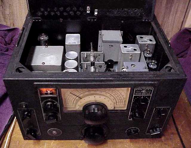
Testing and repair notes
Used Caig Deoxit on all controls and contacts including those on the variable cap. Did a thorough safety check including testing for electrical leakage from the line cord to the chassis. Replaced the wrong oversize fuse with the proper size. Removed the rectifier tube and carefully used a variac to do an initial power up for pilot lights and filaments only. I carefully monitored the current required by the receiver and checked for power transformer heating. Checked for B+ line shorts and leakage using a separate monitored power supply (A Heathkit PS-4 regulated high voltage supply.). This particular set uses non-electrolytic power supply filter caps so there was no need to reform the filter caps.
After I was satisfied with the results of all of these initial tests, I re-inserted the rectifier and carefully powered up the set using a variac while monitoring B+ voltage and current consumption. A 600 ohm to voice coil transformer was used for the audio line to the speaker. With final power up, the receiver came alive and worked very well on the broadcast band with just a hank of wire for antenna. I found that the pins on the coil tray need to be cleaned further since shortwave bands C and D kicked in at either side of the detent but opened when the coil tray is on the detent itself (Follow-up; determined which set of contacts were the problem and did careful mechanical cleaning and adjustment to solve the problem.) The AVC switch needed some troubleshooting. (Spraying a bit more Deoxit directly on the switch while working the switch solved the problem.) Replaced several of the capacitors, including the critical capacitor at the input grid of the 6K6 output tube. (It is critical because leakage can upset the bias and cause the output stage to draw too much current resulting in excess heating of the power transformer. Replacing this cap reduced the AC power draw by several watts. ) This set does not have any capacitors from the power line to chassis. If it had such capacitors, I would typically replace those with modern equivalents rated for AC since leakage can be hazardous.
The IF was correctly aligned on the crystal frequency. The NC-100 alignment instructions call for adjusting the RF and mixer caps in the coil trays for maximum noise while at the high end of each band. A set with 2 tuned RF and 2 IF stages is very sensitive indeed when aligned properly and working well. This set is a tribute to National's design skills, a fine broadcast and short-wave band cruiser.
Identifying the various RAO models
Many of the RAO models have had their Navy nomenclature tags removed. What are the obvious differences between the various RAO models that would enable identification without those tags? The following is a work-in-progress. If you have information that adds to, corrects, or contradicts these descriptions, please let me know.
RAO Manufactured by National , type CNA-46072. Also identified as CG-46072. Mount is identified as type CG-10032.Original Navy Contract date was 10/18/38. antenna input is to a terminal board. This set is identified in SHIPS 242A as an off-the-shelf NC-100A.
RAO-1 Manufactured by National, type CNA-46088 cabinet mount. One RF tube, Uses 6V6G as audio output. Otherwise tube lineup is the same as later models. Navy contract also 1938 . Listed in NAVSHIPS 900,352. antenna input to a terminal board. With only one RF tube, I am assuming this receiver had no "back porch". (the added second sliding coil catacomb that adds an extra RF amp stage and 4 inches to the depth of the other RAO receivers.)
RAO-2 Manufactured by National, type CNA-46187. Uses type CNA-10125 Mount. Has S-meter. No Panadaptor output. Serial number range is 1 - 2721. Listed in NAVSHIPS 900,352. Antenna input to a terminal board with two binding posts. Has top lid on main cabinet. Identified as "National High Frequency Receiver NC-120" on front panel upper right side. Has a "back porch" which is the same width and height and external appearance as the main cabinet, adds 4 inches to the depth but is sealed off. This separately-shielded preselector RF stage was required to reduced radiation from the local oscillator to a specifcation of less than 400 picowatts. The preselector variable cap section is located within the "back porch" and is not easily accessible. V-101, the added 6K7 preselector RF tube is housed in a small module in the main cabinet on the rear wall of the cabinet. Module has a top cover held in place by two vertical stud-bolts. 6K6G/GT audio output tube. Known contract date: 11/20/1943
RAO-3 Manufactured by Wells-Gardner, type CWQ-46187-A. Uses type CWQ-10125A Mount. Same "back porch" as RAO-2. Has S-meter. 115 volts only. Listed in Navships-900, 359-1B. known contract date code 11/18/1943. Has "odd antenna connector". (Navy coax). No Panadaptor output. Uses 6V6GT/G audio output. Identified as "Wells-Gardner Co." on front panel upper right side.
RAO-4 Manufactured by Wells-Gardner, type CWQ-46187-B and CWQ-46187-C. Uses type CWQ-10125A mount. Has S-meter. Same as RAO-3 except 115/230 volts with a jumpering arrangement on transformer to change voltages. Listed in Navships-900, 359-1B. Has "odd antenna connector".(Navy coax). No Panadaptor output. Uses 6V6GT/G audio output. Models RAO-3, 4, and 5 were said to be intended for shore installations. The capability of 115/230 volts makes sense since most of the Allies used 230VAC. Identified as "Wells-Gardner Co." on front panel upper right side.
RAO-5 Manufactured by Wells Gardner, type CWQ-46229 receiver, CWQ-49493 Loudspeaker and CWQ-10125-A mount. 115/230 VAC input. Same "back porch" as RAO-2. Has Navy type coaxial connector antenna input. Connector is straight into back of set (coax is horizontal). No Panadaptor output. Uses 6V6GT/G audio output. NAVSHIPS 900,109 notes"similar to 46187B less 49493 spkr". Identified as "Wells-Gardner Co." on front panel upper right side.
RAO-6 Manufactured by National, Type CNA-46187D. Same "back porch" as RAO-2. Uses type CNA-10125 Mount. S/N 1 through 200 has S-meter, but S/N 201 through S/N 1200 do not. Listed in NAVSHIPS 900,352. Identified as "National High Frequency Receiver NC-120" on front panel upper right side. This is the first model with an SO-239 Panadaptor output. Also has a Navy coaxial connector antenna input in an add-on box. Connector is labeled J-105 in schematic and is mounted in vertical direction on top of add-on box. One writer noted that the added box with the coax connector may have been removed. The antenna binding posts, same as the RAO-2, are visible after removal of the add-on box. "Look for 4 screw holes in back around the binding posts for indications that an antenna box was there." It is possible that upper serial numbers switched to a recessed twist-lock power connector with two blades and a center pin. That power connector is standard on the RAO-7 and up. 6K6G/GT audio output tube. Known contract date: 22SEP1943
RAO-7 Manufactured by National, identified as both CNA-46187D (see RAO-6) and as type CNA-46233. No S-meter. 115 volts. Not identified as the NC-120. This is the first RAO in which the chassis can be pulled out the front for servicing. No "back porch". V-101, the added preselector 6K7, and its variable cap section are housed in a larger module on the main chassis. Module is not painted, has a top lid held in place with 8 screws. Small rack mount pull-handles and capture screws on front panel. Does not have a top-access lid. Has a twist-lock AC power connector. Has SO-239 Panadaptor output. Manual for RAO-7 says"The RAO-7 is the Navy model of the NC-101XA receiver. The main difference being the addition of a second rf stage for reduced radiation from the local oscillator and the omission of the S-meter. The RAO is a general coverage receiver with no electrical bandspread and covers from 540 kcs to 30 mc with an IF of 455 kc." Known contract date: 31MAY1945 (for 1073 receivers and 1073 spare parts sets). Same tubes as RAO-2 and 6.
RAO-8 Have no unique information. Questioning whether it was actually manufactured. Anyone have one so labeled?Archive notes from Moore's 3rd and 4th editions indicate it was Wells Gardner. Other information suggests National. However, info from NAVSHIPS 900,109 Navy Type Number Book, dated September 1945, lists all the other RAO models but skips the RAO-8, as does the Navy 900,116 book.The RAO-7 was Navy Type Number CNA-46233. Navy Type Number Book 900,109 shows the next number as "CWQ-46234 -- RX - CANCELLED".I'd like to know what receiver the CWQ-46234 was. The CWQ coding indicates Wells-Gardner. Was it the RAO-8?, possibly the Wells-Gardner version of RAO-7? Or was it some other receiver?
RAO-9 Manufactured by National, type CNA-46263. No S-meter, Not identified as NC-120. Same tubes as RAO-2 and 6. Has Panadaptor out. Has twist-lock power connector. Has small rack mount pull-handles and capture screws on front panel. NAVSHIPS 900,109 notes "similar to CNA-46233" (the RAO-7). From NAVSHIPS 900,396 (12 Oct 1945) section I, paragraphs 5-8, "Except for minor electrical changes in the grid circuits of the first and second RF amplifier tubes in the RAO-9, the RAO-7 and the RAO-9 are identical." The RAO-7 has the grids of the first and second 6K7 tubes connected directly to the tuned circuits in the sliding coil trays. The RAO-9 has added 30K ohm resistors in parallel with 50 pF caps in the grid feed to those first and second RF amps. NAVSHIPS 900,396 also states that "the RAO-9 is designed to be relatively unaffected by interference from nearby electronic apparatus".
Thanks to Art W6REQ for digging out the RAO-7 and RAO-9 distinction. Opinions on the added parts suggest improved performance in the presence of nearby higher powered transmitters. The components add a bit of grid leak bias to the tubes which, in a high RF environment, reduces the gain somewhat.
The ROA-7 and 9 came in two different cabinet styles. All the RAO-7 and 9 could be pulled forward out of the case. One style has a solid top. The other style adds a top access lid like the earlier RAO models.
Receivers marked "CNA-xxx" indicate National as manufacturer. National also identified internal components such as IF transformers with "CNA-xxx".
Receivers marked "CWQ-xxx" indicate Wells-Gardner as manufacturer. Wells-Gardner did not identify internal components with CWQ. For example the 2nd and 3rd IF's may be labeled just Z-122 and Z-123.