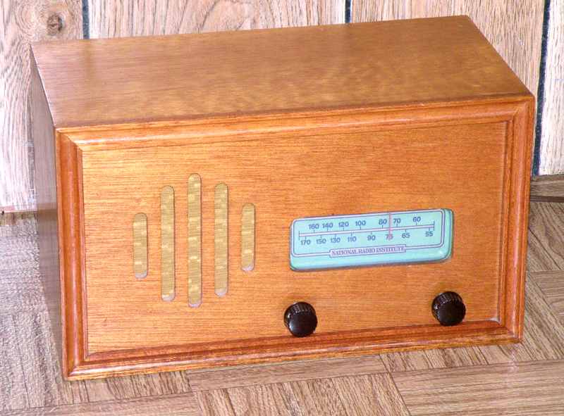
National Radio Institute (NRI) AM radio kit
NRI was well-known as a correspondence school for electronic technician training. NRI also produced a line of kits such as test equipment and a simple Novice ham radio transmitter/ receiver under the NRI and Conar labels.
An unusual set
I first thought the cabinet was an excellent home-brew job. After removing the chassis, I noticed a rubber stamp on the inside bottom of the cabinet. This was indeed an NRI-supplied cabinet which I am told was available at extra cost.
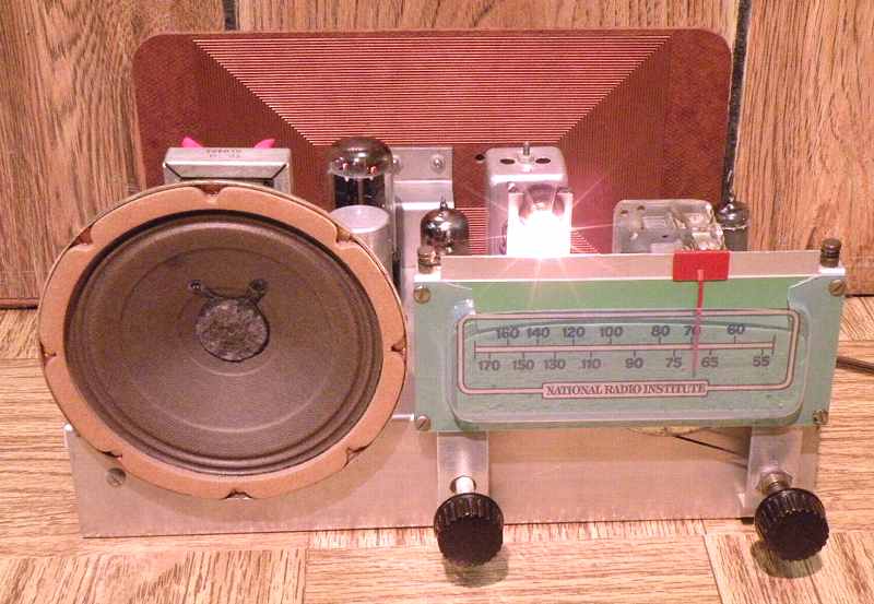
The chassis has IF transformers of two different sizes, several large over-sized resistors, a 12AU7 (dual triode) in place of the usual 6AV6 for detector and audio preamp, a choke in the power supply as a partial PI filter, a negative power source for audio output tube bias, three 1000 ohm resistors in parallel to develop that bias, and some other unusual features. I was wondering if someone had substituted components or simply miswired a couple of items such as the power choke.
Lessons learned
It turns out that ALL of the unusual features were designed into the set. I obtained a paper copy from George K. of the 68 page NRI lesson set 7E1 for this radio titled "Practical Demonstrations of Radio-TV Fundamentals; Instructions for Experiments 61 to 70". The unusual parts were either recycled from previous experiments or were included for a series of tests conducted in the process of building the radio. The tests and experiments include a simulated series of induced faults that are an excellent introduction to radio circuit faults and troubleshooting.
Schematic
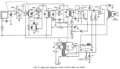
The lesson material includes the full schematic. Click on this small schematic to obtain a larger copy.
Repairs
This set worked as obtained. Even though most of the capacitors in the set were in good condition and did not need replacement, I replaced several caps in critical circuits.
Like many radios built from a kit, alignment was suspect. A quick check with a frequency counter showed that the IF was aligned at 436 KHz rather than the required 456 KHz. Apparently the builder did not have a proper signal generator for alignment. The NRI lessons cover alignment without such a generator, but alignment mistakes are common in these sets.
The pilot light is fixed into a grommet using a metal socket. To prevent short circuits in the event of grommet failure, I swapped connections on the pilot light so that the grounded side was connected to the exterior metal of the lamp socket.
The output transformer primary which carries the full B+ voltage is exposed at its solder terminals. I added heat shrink tubing since I prefer not to have exposed high voltage on the top side of a radio chassis.
The power transformer appeared to be running a bit hot after about 45 minutes. Power draw was 0.48 Amp. After checking voltages and specifications, I determined that the power draw was normal for the design. However, I was not comfortable leaving it that way given present day power socket voltages. I added a choke for choke input and a 200 ohm resistor in the B+ circuit. This reduced the power draw to 0.43 Amp, about a 10% reduction. The maximum B+ is now 309 volts, down from 345. The reduction had no effect on the radio other than reducing heat build-up.
Performance
The NRI booklet notes that the radio, when properly constructed and aligned is equal in performance to better commercial sets. It is indeed. The tuned RF stage with a standard superhet set performs quite well at pulling in distant weak stations. The lesson does not mentioned the single turn wire around the outside of the antenna loop. If even more sensitivity is desired, that turn is for connecting to an external antenna.
NRI's later set
I purchased this set at a swap meet because it was a "cut above" with its 3 gang tuning cap for tuned RF stage and its power transformer. This set was apparently an earlier version provided by NRI in the early 1950's. I was familiar with a later NRI set that was strictly a cheaper AC-DC version with no tuned RF stage. I'm left to wonder why they quit using this excellent set in favor of that cheaper version.
8-25-09
An Eico HF-87 Stereo Power Amp was the previous item on the bench.