National Schools AM/SW radio kit
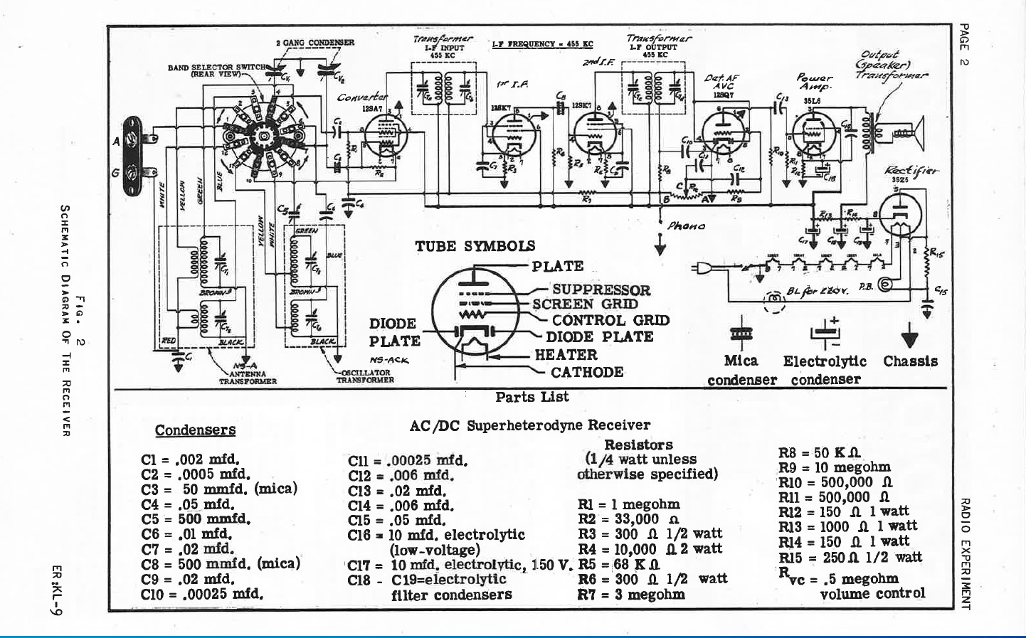
The National Schools radio is the octal tube version of the "All American Five" plus one, an added second IF tube. The radio has tubes with the filaments wired in series using a 35Z5 rectifier, 12SA7 converter, two resistance-coupled 12SK7 for IF amp, 12SQ7 for audio preamp, AVC and detector, and 35L6 for audio output.
Like some other kit radios offered through home-study courses, this radio has a relatively dangerous "hot-chassis" design with one side of the power line switched to the chassis. Depending upon the orientation of the power plug, that makes the radio chassis "hot" either when switched on or when switched off (by way of the cold tube filaments.) In years past this circuitry was common and the danger was well known. However, in today's rechnology nearly every metal plug-in device such as a desktop computer has a safety ground attached. That safety ground connects to the neutral side of the power line at the breaker box. Touching a hot chassis and a desktop computer at the same time can be a dangerous shocking experience. I added an isolation transformer to this radio to eliminate the danger.
Homebrew cabinet
The cabinet is a simple home-brew version made of plywood and painted gloss black. Holes were drilled into the top for sound from the 8 inch speaker.
Repairs
After safety checks, application of deoxit on the bandswitch and volume/ power switch, tightening ground screws, and replacing two critical caps, I powered up the set with my isolated variac. This set worked to some extent. However, alignment was off considerably and the set would break into oscillation or motor-boating intermittently. It was especially sensitive to oscillation when the antenna wire was disconnected, but shorting the antenna terminal did not stop the problem. Bridging the electrolytics made no difference. A wire into the shielded antenna coil can had some insulation missing. I pulled the shield can and replaced the wires. No change in symptoms. As with any kit, I wonderered if it had been wired correctly. I also did not have a schematic at the time.
I stumbled upon the cause of the oscillation while doing some resistance checks. I had tightened all the ground screws at the outset since this was an aluminum chassis. I should have checked the results with an ohmmeter. Checking resistance against one of the ground points proved that two ground lugs that were attached with tube socket mounting screws for the 12SA7 and a 12SK7 were high resistance contacts. Definitely not grounded. I could have replaced the screws and star washers but instead decided to run a simple ground bus wire to those points. That solved the problem permanently.
Besides the two critical caps (power line to ground cap and cap to the input grid of the 35L6), I replaced several other caps that see high voltage. Surprisingly, the old wax caps were actually still quite good when tested.
To solve the hot chassis problem, I decided to add a permanent isolation transformer to the set, mounting it directly on the cabinet inside wall. A three-wire grounded power cord was added to the set and the power switch rewired to the primary of the added transformer.
Alignment
Alignment was definitely needed. IF alignment was close to 455 KHz which I assume is the correct IF frequency. After determining which alignment trimmer was which, I aligned the shortwave. Tracking was good. The broadcast band has a padder which I am not sure is original. I was able to adjust the trimmer and the padder so that most of the band came in at the proper points on the dial but the tracking at the lowest end of the dial is relatively poor.
Performance
Performance of the set after repairs and alignment was actually quite good considering the fact that this is a basic set. Sensitivity is excellent on the short wave band and most of the broadcast band. The dual tube IF stage helps with sensitivity.
The National Schools ads show this radio and its chassis in several different stages which were linked to course lessons KL-1 to KL-9.
Schematic and Pictorial
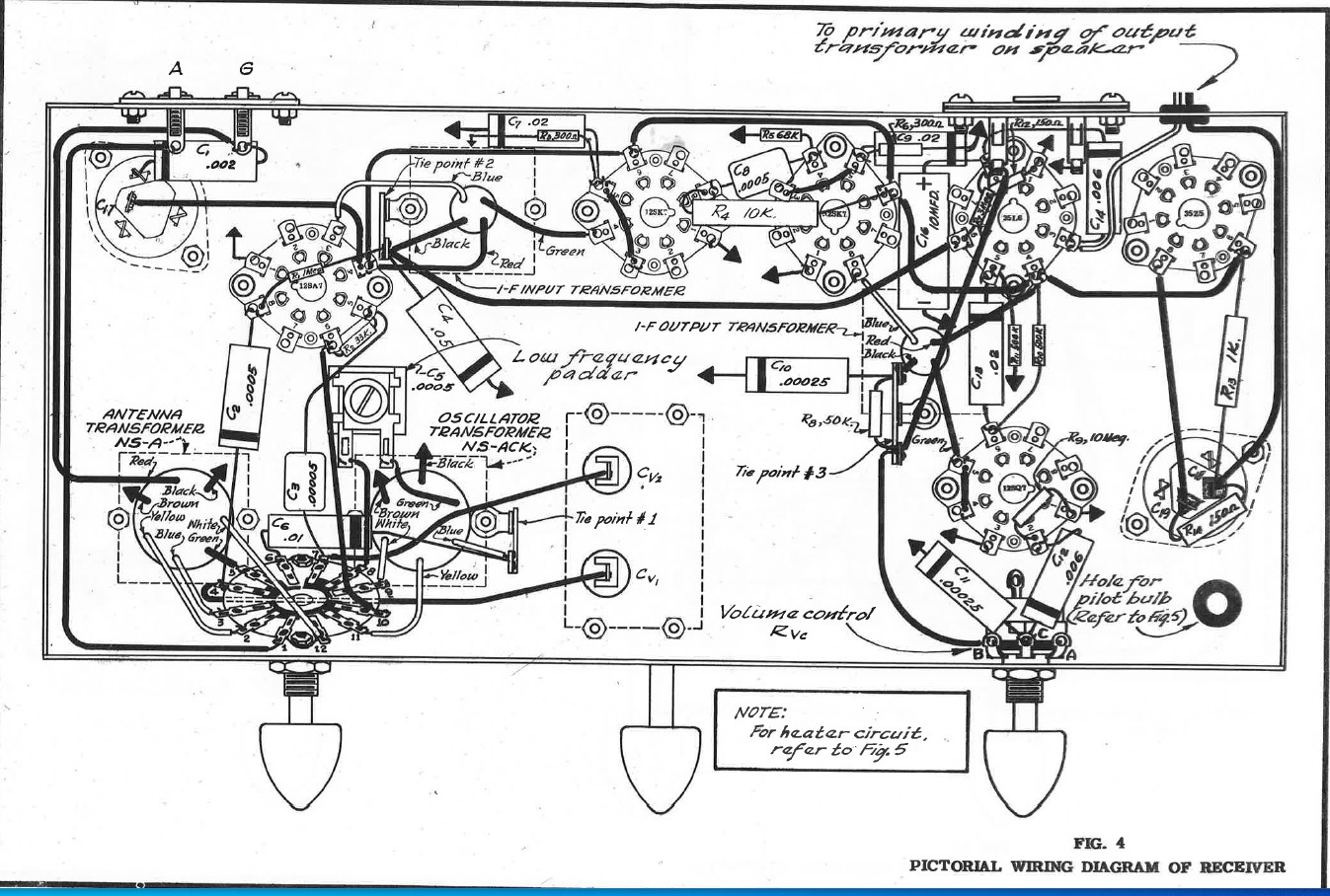
I have recently received the original related National course lessons courtesy of Matt Potter and a week later received excellent copies of the schematic and pictorial courtesy of Dan Pace. Copies are here thanks to Matt and Dan. Right-click and "save as" to download the full page copies.


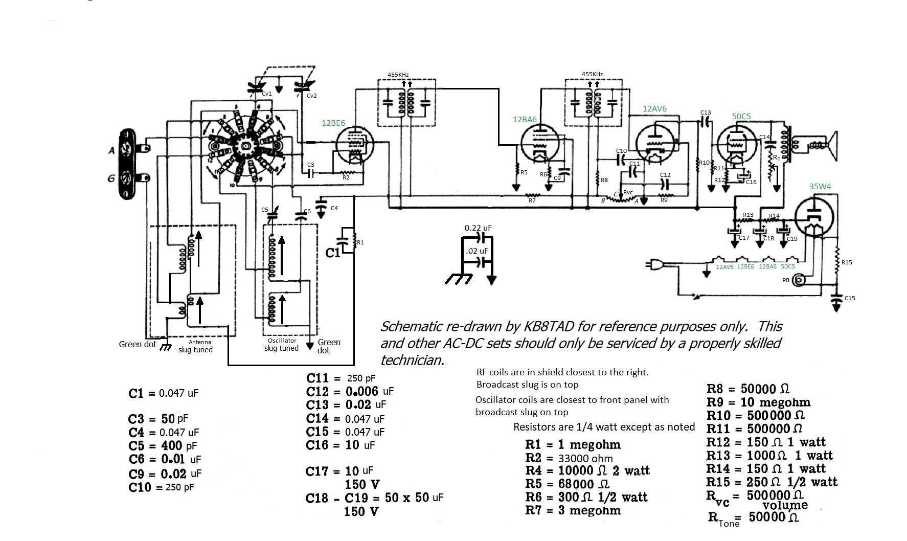
Schematic for the newer KL-9
National Technical Schools introduced a newer kit in the 1960s.
I have redrawn the older kit schematic to conform to that later set and published a column on that set, model KL-9, in The Spectrum Monitor, June 2021. (right click for full size copy)

Other home-study schools radios and chassis on this website.
I have repaired and documented radios and other kits for several home-study schools.
A list and links to those home-study kits can be found here.
7-29-12, update 4-16-21, 5-29-21
A Hallicrafters S-41G "Skyrider Jr." receiver was the previous item on the bench.