Condition as found
The cosmetic condition of this black wrinkle scope was excellent as purchased. On checking the scope with an ohmmeter, I discovered that the power line input was directly connected to the metal case. Further checks revealed that the power transformer's high voltage winding, one side of which is connected to ground in a half wave circuit had faulted to the AC input. The power transformer is a sealed unit from National with the core embedded in tar. I could probably have added an isolation transformer to the unit but I did not want to take chances. I removed the power transformer, pried out the small brass ferrules that held the bottom of the transformer housing onto the case. Then heated the transformer to soften the tar so the wires could be moved somewhat. Had no luck solving the short circuit problem. I heated the transformer housing some more and very carefully removed the entire contents from the housing. The tarred transformer had a cardboard sleeve between it and the transformer housing allowing relatively easy removal.
Repairs
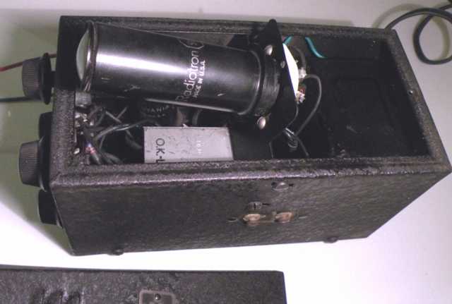
I decided to substitute a smaller transformer in the now-empty National transformer case. The replacement smaller transformer supplied only 160 Volts AC but had the needed 6 volt winding for the filament. I mounted it on a perf board along with a couple of diodes and capacitors for a half-wave voltage doubler that could provide a no-load DC voltage of about 160 X 2.8 = 448 volts. The positive side of the supply would be grounded. The entire assembly was placed into the empty transformer housing surrounded by insulating sleeves. The 6X5 would still be in the scope but no longer used.
The two high voltage pots for intensity and focus were opened for an application of deoxit. The horizontal level pot and the horizontal input switch were also cleaned and checked for function. The existing filter capacitor was checked at full rated voltage and determined to be OK for further use. I replaced the transformer wiring but used old-style black-braided sleeving to cover the new wires. A casual glance either inside or outside of the scope still shows it in original cosmetic condition.
The original power transformer had also used a tap on the the high voltage AC winding to feed the horizontal width control with 60 cycle AC for sweep purposes. I used the AC high voltage of the new transformer in similar fashion but added a 68K ohm resistor in series to limit current in case of a horizontal width control short circuit.
A check of the replacement transformer filament voltage showed it a bit high. Not wanting to shorten the life of the 913 tube, I inserted a 2 ohm power resistor in series which brought the filament voltage down to the proper 6.3 VAC for the 913 filament load.
I substituted a safer 3 wire grounded power cord for the original. I suspect that the high voltage-to-line fault of the original power transformer was likely caused by arc-over between the transformer windings by a high voltage spike, possibly from RF, seeking ground. A case that is grounded at the power plug provides a low impedance ground return and could prevent a similar fault.
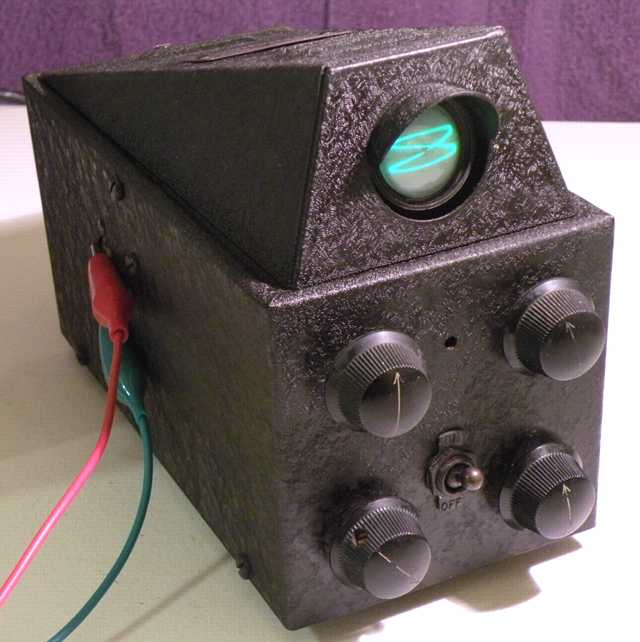
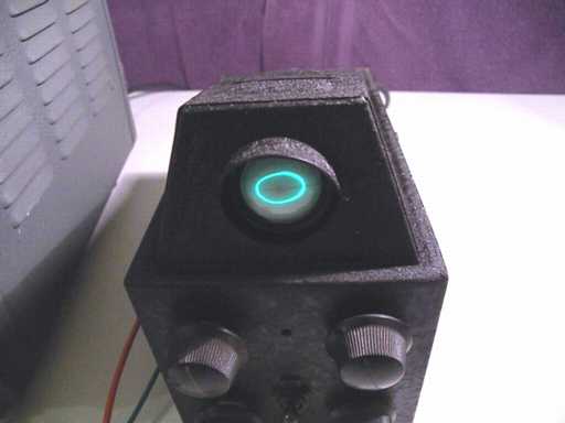
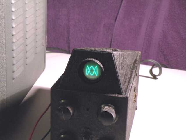
Since the replacement half-wave voltage doubler circuit used solid state rectifiers, it was easy to use a variac to ramp-up and test the high voltage before inserting the 913. After verifying that the high voltage was functioning properly, I inserted the 913 scope tube and was gratified to see a small green horizontal line that could be focused properly. The horizontal input is optionally fed with 60 cycle AC and width is adjustable via the horizontal width control.
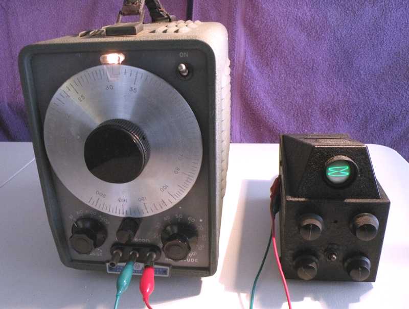
Playing with the CRM, Lissajous figures
As noted, the CRM uses 60 Hz frequency as an option for its horizontal sweep. The dial on the Hewlett-Packard HP-200AB audio oscillator shown above indicates 31 Hz for the vertical input. It is off by one Hz. The Lissajous figure shows a vertical 2 to 1 image indicating 30 Hz vertical. Here are a couple of other Lissajous figures. Determine the frequency of the HP oscillator for each picture. (Answers below)
Further info on the National CRM
The RCA datasheet on the 913 tube is available from Frank's tube info site (see my homepage) and has a good basic schematic. The 15th edition of the ARRL Handbook (1937) shows a very similar scope circuit using the 913 tube on page 381.
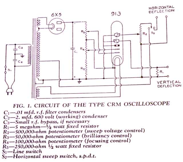
James Millen wrote a small book in 1938 titled Notes on Amateur Transmitter Design that includes a section with the manual on the National CRM scope. The notes include the following schematic:
A Conalert II Conelrad monitor/receiver was the previous item on the bench.