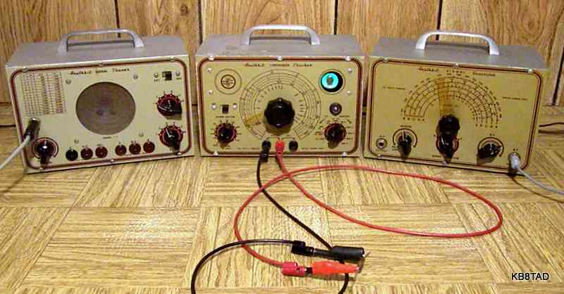
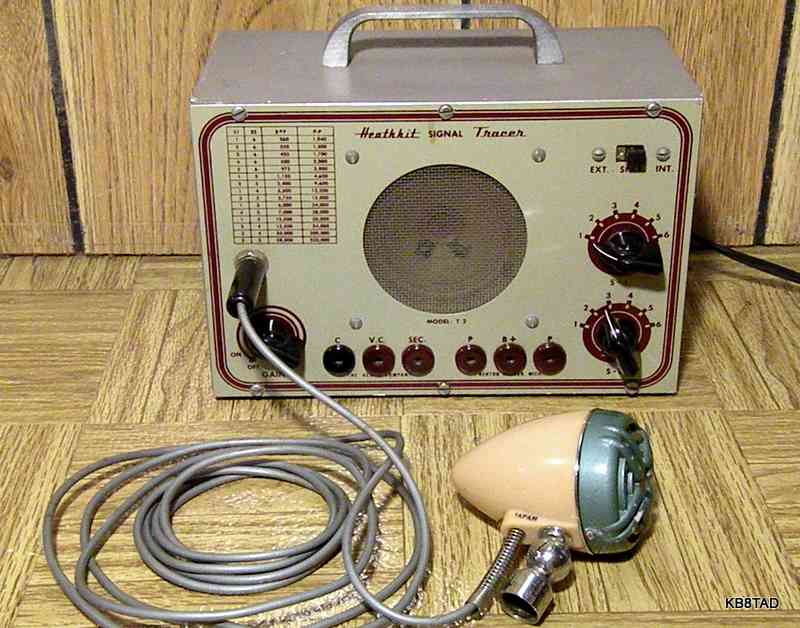
Heath started advertising surplus electronics in Radio News magazine in August 1947. In the November 1947 issue, Heath advertised its first kit, an oscilloscope made partly with surplus parts. Heath soon followed up with other test equipment kits using inexpensive surplus parts wherever possible. Their first RF signal generator model G-1 first appears in the January 1948 issue. The first Condenser Checker model C-1 appears in the March 1948 ad along with the first signal tracer, model T-1. The signal tracer shown here is model T-2, the second generation for its type. It differs from model T-1 with the addition of a very useful impedance-selectable audio output transformer and test speaker. The first ad for the T-2 appears in the April 1949 issue.
Repairs
The T-2 needed replacement of nearly all the capacitors including all that see any appreciable voltage; coupling, bypass and electrolytics. I polarized the line cord plug so that the hot side goes directly to the power switch and the neutral to the transformer.
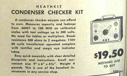
Heathkit C-1 Condenser Checker
The Heathkit C-1 uses a 12A6 as rectifier and a 1629 eye tube. Both tubes were surplus when the set was designed. Resistance and capacitance are measured in a direct-reading bridge circuit. The eye opens when the correct resistance or capacitance is selected by way of the main dial potentiometer. As with all such bridge devices, accuracy is dependent on the precision of the standard capacitors and resistors in the device.
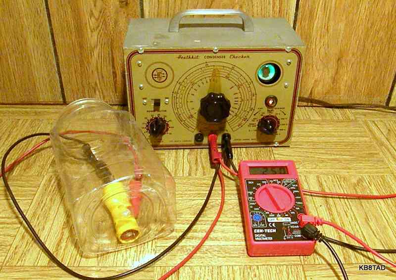
Since measuring resistance and capacitance is relatively easy with modern instruments, the Heathkit C-1 now finds its best use as a means for reforming electrolytics and testing capacitors for leakage under high voltage conditions. The test leads for the C-1, as in most capacitor testers of its kind, have high voltage applied during tests. I like to know what the test voltage is and therefore typically use a voltmeter in parallel with the capacitor during reforming and leakage tests.
The picture above shows an electrolytic being reformed in step-wise fashion. The neon bulb (below the eye tube) lights when the reforming current is about 2 mA or more. The reforming process starts with the voltage step switch set at the lowest voltage at which the neon bulb lights. As reforming progresses, the neon bulb will go out when reforming current drops below 2 mA. At that point the next higher voltage step can be selected until the capacitor shows full proper voltage on the voltmeter. Note that the cap and the exposed test lead clips are in the plastic jar for safety. When the reforming process is complete, I turned the tester's power switch off and moved the step switch to the "R" setting to quickly bring the voltage across the capacitor back to zero. The "R" setting places a 1000 ohm resistor across the test leads.
Repairs consisted of replacing nearly all of the capacitors. The resistors were off as well. The standard bridge resistors were replaced or adjusted by adding appropriate parallel resistors.
The larger power-divider resistors for the voltage step-switch were each high by about 5 to 15%, but well within the 20% specification. I opted to add resistors in parallel to bring them back close to their intended resistance. I only had the schematic for the C-2 which has the same power supply and step voltage dividers as the C-1. I added a resistor to the chain to bring the no-load voltages of the step divider to within about 5% of the target. The 20 volt step setting cannot be achieved as designed per the schematic and will typically show a no-load voltage of about 100 volts. I do not recommend using the C-1 (or a C-2) to reform electrolytics of voltage ratings less than that.
Sometime later, I found the C-1 schematic and C-1 the parts list . Click on the links to see them.
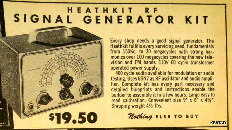
Heathkit G-1 Signal Generator
The Heathkit G-1 provides RF output from 150 KHz to 34 MHz in 5 ranges. The dial has the third harmonic of the highest band calibrated to 102 MHz. The G-1 was obviously designed with surplus sealed capacitors with two of them prominently mounted on the chassis. The first high voltage filter cap is a 1 mF sealed cap. Tubes are 6SN7 as the oscillator and amplifier and 6X5 as rectifier. The 400 Hz modulation audio is generated by a neon relaxation oscillator fed to the grid of one section of the 6SN7.
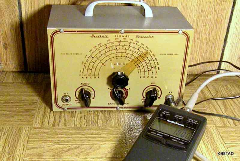
The design of the G-1 allows for tweaking each of the 5 bands with individual trimmer caps. None of the later Heath low-end signal generators have that feature. It allows the set to be calibrated to surprising accuracy for its price class.
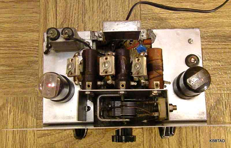
Repairs
The main problem with the G-1 was a power transformer with what I determined were shorted turns on one side of the high voltage secondary. The transformer, mounted under the chassis, heated very quickly even with no load. The condition was not new as significant dried wax had oozed out of the open frame transformer and onto the base of the cabinet. I found a suitable replacement that was the same physical size as the original. The caps are mostly micas and did not need replacement. The sealed cap B+ power filter was determined to be too small to do the job. The modulation had a fairly harsh note and the B+ voltage was low. Both problems were solved by replacing the power supply filter with a modern 47 MFD from the junk box.
A steady hand is needed for setting the dial as the tuning cap is direct with no vernier. I found the G-1 to be surprisingly accurate and relatively stable. Teamed with a frequency counter, it is a very usable piece for servicing antique entertainment radios.
Signal generator generations through the 1950s
The G-1 was followed by the G-5 which rewires the neon oscillator connections a bit to allow for external audio input as well as audio out. It also adds a 5 to 1 vernier dial and has an upgraded highest frequency coil. It drops the individual trimmers. The in-between model numbers are G-2 and G-3 which are an audio generator and a sweep signal generator. I do not yet know the details of the G-4.
Schematics
Check this site for other Heathkit schematics.
11-6-10; updated 11-3-15
Two Homebrew 6SN7 QRP Transmitters were the previous items on the bench.