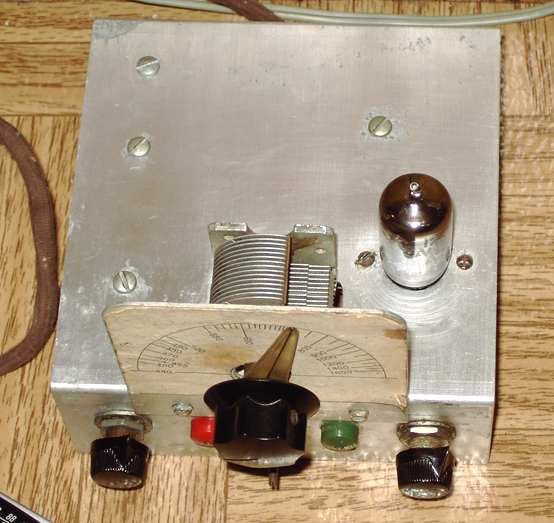
Mystery chassis top view
Mystery RF-AF Oscillator Chassis
has been identified
At ham radio swap meets, known as "hamfests", I'm attracted by simple one or two tube homebrew chassis, often just to satisfy my curiosity about what the circuit was designed to do. I also keep an eye out for chassis that could be re-purposed to make regenerative receivers or similar fun projects.
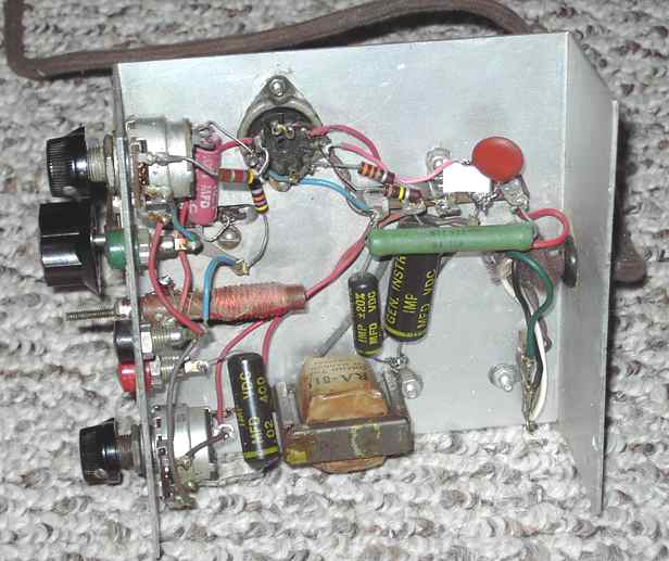
This little one-tube chassis measures 5 inches square. It is definitely NOT homebrew. The tube socket and control holes and the slot openings for the tuning cap are factory-punched. It was likely part of a home-study electronics course. It's purpose was as a signal generator for frequencies that included common IFs as well as the broadcast band. It was missing its tube. I sketched a schematic of the unit as found. From the wiring, I determined that the missing tube was probably a dual triode 12AU7 or plug-compatible such as 12AT7 or 12AX7. Its power umbilical has color-coded wiring and terminates in four phone tips, two for the filament and one each for ground and B+.
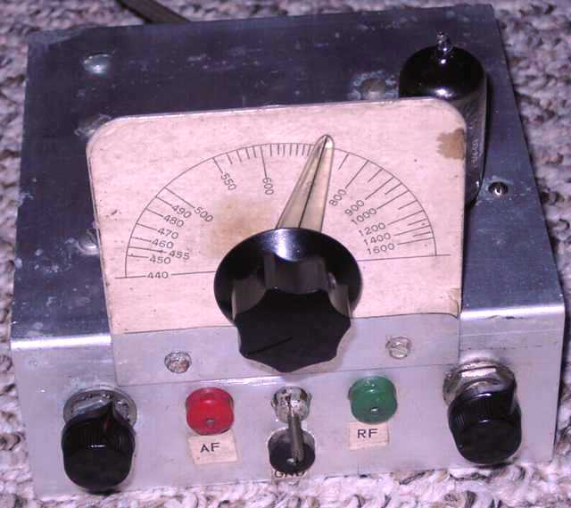
One of the triode sections has a classic cathode-connected tapped coil. The variable cap dial is marked for 440 to 1600 KHz as an RF oscillator. The other triode is an audio oscillator/ modulator using a small choke. As found, the choke was not connected on one side. When powered, neither side worked. Both sides were missing the feedback caps to the grids. The audio side also was missing a frequency-determining cap to ground.
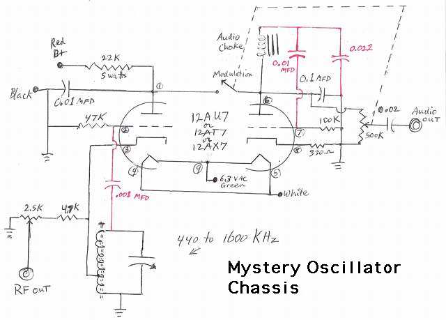
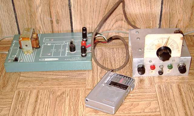
With those three added capacitors (marked in red on the schematic), the little unit worked fine, a nice signal generator for AM broadcast and common IF frequencies. The single-tone audio oscillator/ modulator can be used directly for audio work. With the capacitors selected, the audio side shows a nice clean sine wave on the scope at a frequency of about 450 Hz. A little Heathkit EF-1 power supply provides filament and B+ power.
I have given thought to re-purposing it as a broadcast-band regenerative receiver or a wireless broadcaster. However, I wanted to identify its maker first. I assumed it was part of a home-study electronics school.
Mystery chassis identified.
Bob KL7FM was the first person to identify this piece. According to Bob, the piece was part of a course from RCA Institutes, Inc. The power for this chassis was supplied by an oscilloscope which was also part of the course. The scope, model number 54-45, has pin jacks on the rear panel which correspond to the power needs of the little chassis. The scope provides 400 volts DC at 20 mA. and 6.3 VAC at 300 mA.
According to Bob, "I put one together around 1967... The o-scope was also in kit form. I used the little oscillator in various experiments and also to align table top radios." Bob forwarded. a link with pictures of the scope . The linked site to the scope has a further link to the scope manual.
 <
<Another Hewlett-Packard HP-400C AC VTVM was the previous item on the bench.