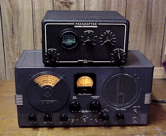
Panoramic Radio PCA-2 T-200 Panadaptor
Introduced in 1946 by the Panoramic Radio Company, this was also sold by Hallicrafters as the SP-44 Skyrider Panoramic . The earliest manuals for the Panadaptor were done on ditto machines (this looks like purple typewritten material). Later manuals were printed. The SP-44 uses a different style for the knobs and different logo on the front panel.
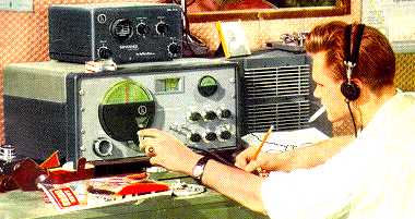
The Smithsonian Science Service Historical Image Collection
shows an early picture of the Panadaptor connected to a Hallicrafters S-20R.
That picture inspired this one.
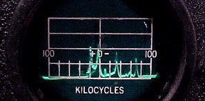
The Panadaptor is a spectrum display which portrays visually the signals in a selected part of the radio spectrum. It is connected to a receiver's converter at the input of the first IF amplifier stage. Connecting at a further point reduces the spectrum width. This unit is designed for a 455 KHz (or near) IF. The signal being listened to is placed at the center of the display. Nearby signals are also displayed as pips of varying shape to the left and right of center. Pip shapes vary with the type of transmission. For example, CW signals produce a very narrow pip.
Had to reduce the voltage of the replacement transformer a bit. Added a 100K resistor at the input of the voltage doubler. Used choke input on the B+ side to reduce its voltage. This also cut down on current consumption. Transformer gets warm after a time but not hot. I have determined that the dittoed manual called for lower voltages in my older version. Had to troubleshoot a noise source that turned out to be spurious oscillation in the 6AC7 oscillator circuit. Found that the 3000 ohm plate resistor had gone DOWN in value to about 200 ohms. Replaced resistor and followed up with a thorough alignment.
Circuit variations
There were two variations in the CRT in these sets. This earlier one uses a type 902A CRT with an octal socket. The 2AP1A is a later CRT using a larger socket. A later model variation used a tap on the transformer high-voltage secondary in place of a separate additive winding. A sync control was added under the chassis. The center frequency control circuit was greatly changed. The metal case for this early version has fewer ventilation perforations than some of later vintage. Note that despite these changes and a number of circuit updates, the model number remained the same.
BAMA has the Panadaptor manual in PDF format
The Hallicrafters SP-44 version was pictured with the SX-42 on the cover of the March 1947 Radio News magazine (below).
The manual for the Hallicrafters SP-44 can also be downloaded from BAMA.