Navy RBG-2 by Hammarlund
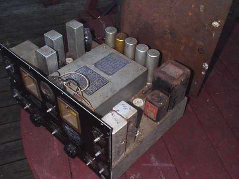
My initial response to this set was parts radio. It came with most tubes missing, no bottom plate, most knobs gone, capacitors hanging loose, other parts missing, and a section of ceramic bandswitch that was cracked. Also note the color of the cabinet sitting behind the chassis. Cosmetically, the front panel was a mess that had been poorly repainted earlier in its life with small portions sandpapered and the paint around the knobs thoroughly scratched. However, the auction price was appropriate to its condition as parts radio.
The Navy RBG-2 is also identified as type CHC-46140. Built by Hammarlund during WW II, it is a transformer-operated, single-conversion, general coverage receiver covering the broadcast band through 32 MHz in 6 bands. The set is a variation of the Hammarlund HQ-120 built to Navy specifications. Among the changes for the Navy are transformers and chokes that are potted and sealed (see the power and output transformers at right rear of chassis), a very different tube line-up that has more in common with the post-war HQ-129, and power supply filter caps (all 5 are visible at the rear of the chassis) that are not electrolytic. The audio output impedance is 5000 ohms for the speaker with a separate balanced center-tap-grounded 600 ohm output for headphones. There are several other changes unique to this model, especially in the audio and S-meter circuits. Bandspread dial frequency markings are to Navy requirements.
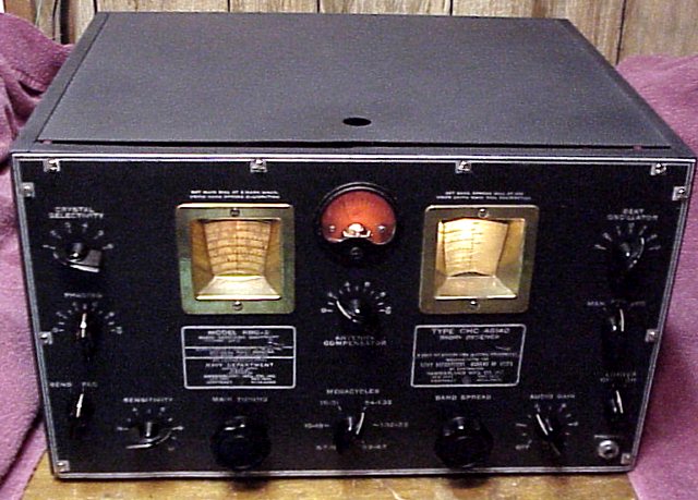
Repair notes: After determining that the radio could and should be repaired, the front panel was stripped to bare aluminum and repainted again. The lettering which is slightly raised on the panel was painstakingly restored by using a motorized rotary ink eraser to remove the paint. Touch up was with very fine artist's brush. The result was protected by 2 coats of non-glare clear acrylic. The resulting panel is decent looking. The case was refinished. I located a piece of aluminum to substitute for the missing bottom plate.
While the front panel was off, I also removed and cleaned the tuning dials, and cleaned and lubricated the variable capacitor gearing. The variable cap gear preloading (split gears with a spring to keep tension on the gears) was reduced from what I had found initially and the result was much smoother tuning with reduced tension on the plastic dials but still without any backlash. I suspect that the preloading may have been increased by a previous owner. All switches and pots were cleaned with deoxit.
Although the brass tuning dial escutcheons are typically painted black, the ones on this set had never been painted. Cosmetically, I just polished them.
Electrically, the largest missing component under the chassis was one of two chokes. I located a non-potted choke of the proper specs but not the same physical dimensions. I was able to mount it in place of the original using existing holes. Practically every capacitor had to be replaced. The chassis-mounted potted caps were left in place but are no longer connnected. Inexpensive ceramic caps were used for bypass purposes. The small electrolytic caps that a previous owner had wired under the chassis and left hanging loosely on wires were cleaned up and mounted on a terminal strip. A three wire power cord was installed. The original 0.1 mike sealed caps for bypassing the power line, though not leaky, caused the GFCI on the bench to trip. I replaced these with a smaller value cap rated for line voltage. Some other previous owners' changes, for example a clump of three resistors in parallel, were corrected. The cracked ceramic section on the bandswitch had been poorly repaired earlier with some type of glue that had cracked and dried. The old glue was carefully removed, the broken piece properly reseated, and slow-set epoxy used for a successful repair.
The RF alignment was way off on all bands. However, once aligned and a variety of electronic problems solved, I was quite pleased with the performance of this set. Its dial markings are quite accurate, and it is very sensitive. I did not have to do major alignment on the IF chain as it was properly aligned to the crystal frequency.
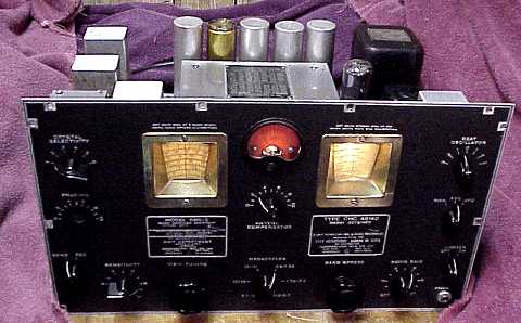
As can be seen in the middle picture, the crystal phasing control was missing. This is a common problem encountered on this set and its HQ-120, HQ-129, and SP-200 relatives. The phasing control shaft is made of phenolic and breaks easily. I cut and shaped a phenolic replacement shaft and epoxied it to the phasing cap shaft stub.
Notes on power consumption
I made a few measurements of power draw versus line voltage on this set. RF gain was set at maximum.
The Lafayette HE-60 was the previous item on the bench.