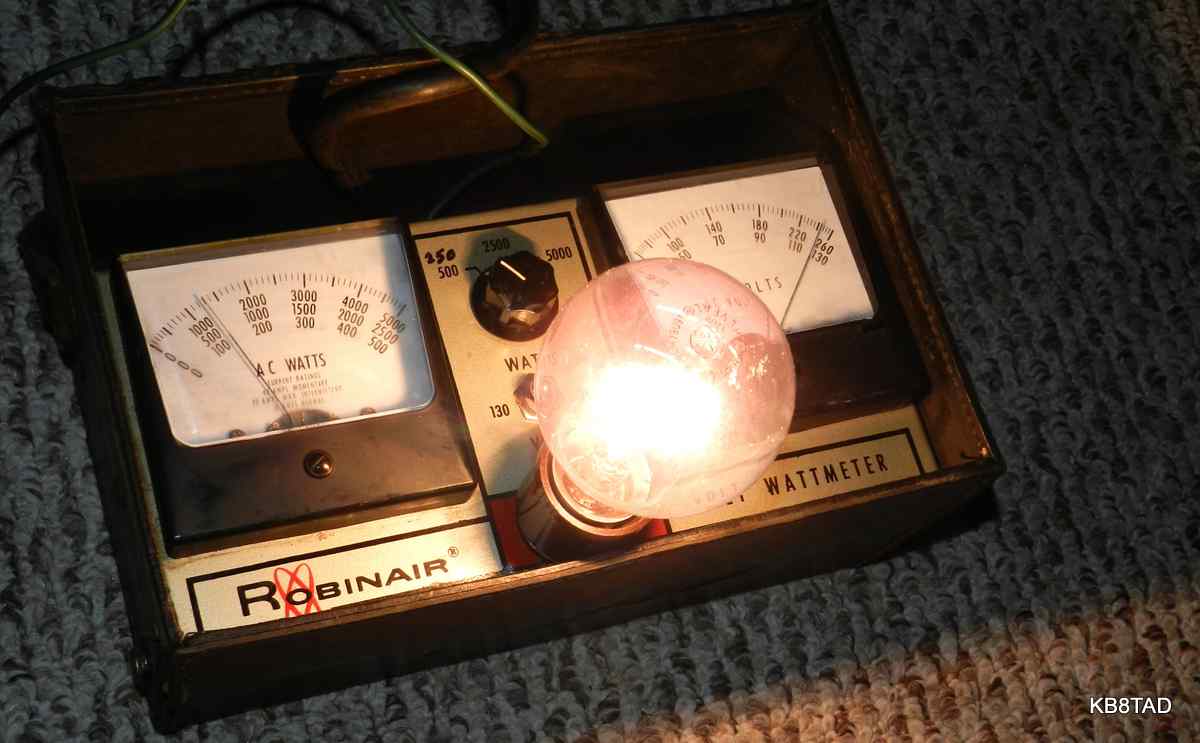
One of the devices I had been casually looking for is a proper wattmeter for measuring the power draw of various boatanchor radios and amplifiers. While a separate voltmeter and ammeter are useful for measuring volt-amperes, an electrodynamometer style of wattmeter is more accurate especially for non-resistive loads. When this one came up for auction, I decided to get it and try it out. As it was, the auction price was quite reasonable probably because of the relatively high ranges.
The Robinair Voltmeter-Wattmeter was designed for appliance servicing as is obvious from the ranges. The lowest range is 500 watts. The other ranges are 2500 watts and 5000 watts. The two voltage ranges are 0-130 volts and 0-260. It comes with a grounded three-prong cord and a matching three-prong outlet on the front panel. A separate green wire with an alligator clip is attached for grounding any appliance being tested.
In servicing boatanchor radios, I obviously didn't need the 2500 watt or 5000 watt scales or even the 260 volt scale. My thought was to study the circuit and change the lowest scale to something on the order of 250 watts so I could use the 2500 scale and simply divide by 10. Would that be possible?
Checking out the circuit.
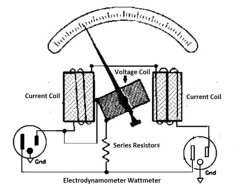
An electrodynamometer direct reading wattmeter uses a pair of fixed coils for current and a moving coil for voltage. It generally has four different terminals although one terminal could be common, therefore requiring only three.
I was not able to find a schematic for the meter. I pulled the meter from the housing. The voltage switch, when switched to the 130 volt scale simply shorted out one of two series-wired dropping resistors. On the wattmeter side, I found three small rheostats for calibration of the three scales and three dropping resistors, all in series. The range switch simply selects one of the rheostat output legs. The internal resistance of the voltmeter side within the wattmeter itself measured at 450 ohms. A 3.9K ohm resistor led to the first rheostat which measured 1630 ohms to its paint-fixed factory-adjusted setting. This first rheostat was wired to the 500 watt switch terminal. The next resistor measured at 18K ohms which led to a rheostat setting measured at 6K ohms which connected to the 2500 watt range switch terminal. This was followed by a 15K resistor and a rheostat with a measured resistance setting of 14K which led to the 5000 watt switch terminal.
Modifying the meter
After several simple experiments to change the lowest wattmeter setting to 250 watts, I ended up wiring a 1000 ohm resistor in parallel with the 3.9K first resistor. Just a slight tweak of the first rheostat was necessary for proper calibration of that new range. The 2500 watt range rheostat was adjusted also to compensate for the now reduced resistance in what had been the 500 watt range.
The AC voltmeter
The main voltmeter read about 6% high. I wanted better accuracy than that. I measured the voltage directly across the meter at 28 volts, while its dropping resistor took up 86 volts. I ended up adding 820 ohms in series with the meter using a pair of resistors in parallel, a 1K ohm and 4.7K ohm. That brought the accuracy of the voltmeter on target.
Operation
Although the Volt-Wattmeter has the 2500 and 5000 watt ranges, the instructions note that the maximum typical draw is 10 amperes. I assume the 5000 watt setting may be for momentary observation of motor-starting draw. If you have a schematic for the meter, please share.
If I decide I still need the 500 watt range, I will add a switch that will kick in the added resistor in parallel only when the 250 watt range is needed and add a separate little rheostat for accurate adjustment of the added range. My experiments proved to me that with simple modification, the addition of resistors or a separate adjustment rheostat, this piece would indeed prove to be a very useful wattmeter for my testing purposes.
date: 4-23-15
A Pyramid Phase III model PS-25 High current low voltage variable power supply was the previous item "on the bench".