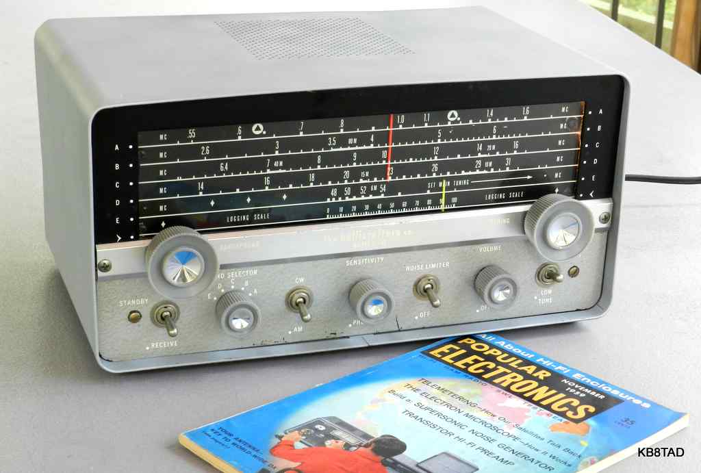
Hallicrafters S-107 receiver
The five band Hallicrafters S-107 uses seven tubes and is transformer operated. It covers the broadcast band, three short wave bands from 2.5 MHz to 31 MHz and the six meter band from 48 to 54.5 MHz. The receiver has dual IF amplifiers but does not have an RF amplifier stage. Offered from 1958 to 1962, the radio was a replacement for the S-53A.
Three versions
There were three variations of the S-107. Tubes in this 2nd version (S-107 Mark I) include a 6BA6 as mixer, two 6BA6 as IF amplifiers, 12AX7 as audio preamp and BFO, 6AL5 as detector/ AGC, 6K6 as audio output and 5Y3 as rectifier. The earlier version (S-107) used a 6H6 in place of the 6AL5 and a 6SC7 in place of the 12AX7. A later version (S-107 Mark II) substitutes a 6AQ5 in place of the 6K6. This Mark I version and the oldest version have an RCA jack as phono input. The Mark II version uses that RCA jack for audio output. This Mark I version and the oldest version use tip jacks for headphone output. The Mark II version uses a phone jack.
Condition
As purchased, the face of the S-107 was in generally good cosmetic condition but the cabinet showed some corrosion along the top back end. The main tuning control did not move the pointer. The dial cord had broken. A former owner had modified the rig and installed a second RCA jack in parallel with the headphone tip jacks, probably for an external speaker. That modification was useful and neatly done so I decided to leave it in place.
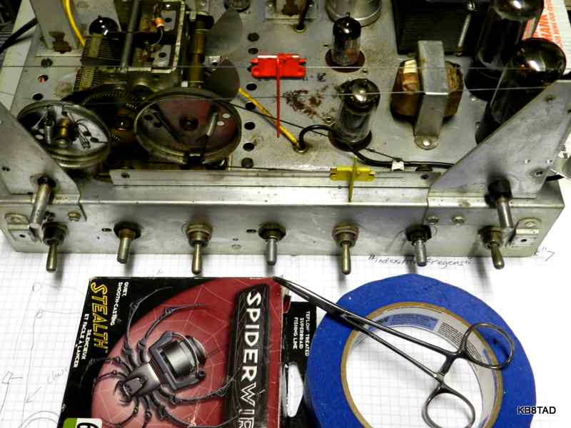
Tuning Dial Cord
After a thorough cleaning and some unpowered safety checks (for possible power line leakage to chassis and for proper resistance in the B+ line), I decided to tackle the broken main tuning dial cord. The stringing diagram can be found on the BAMA manual site. The chassis front has to be disassembled to get access to the pulleys and spring. I used a nail punch to loosen the knurled nuts on the switches.
Repairs
At this point, I powered the set slowly, checking current draw carefully. I was able to hear the two local broadcast stations with the sensitivity and volume controls at maximum. Overall sensitivity was extremely weak. The audio section when checked had plenty of gain.
I checked voltages to see if perhaps one of the IF tube screen grid resistors had opened. No voltage problems found. I next checked the tubes. All checked fine. I next checked alignment.
With a 455 KHz signal injected, the IF adjustments improved the gain slightly but were quickly maxed out not allowing them to peak. At this point, I got suspicious. These IF transformers were the miniature variety. There had been no crackling or other noise as a sign that the little mica caps inside might be breaking down, and I had not detected any DC voltage on the secondary side of the IFs. However, placing a voltage prod on the plate side of the first IF had caused an increase in sensitivity indicating a possibility of too little capacitance. The same thing happened with the voltmeter not connected, just the prod and its wire. I decided to open the IFs and see why they would not peak.
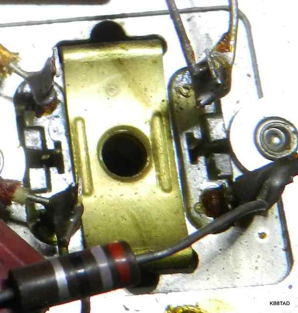
Silver mica disease
With the chassis upside down, I made notes on the wires and components connected to each IF terminal. I also noted the location of the little green mark on the one grid input terminal (barely visible green mark next to the upper left terminal).
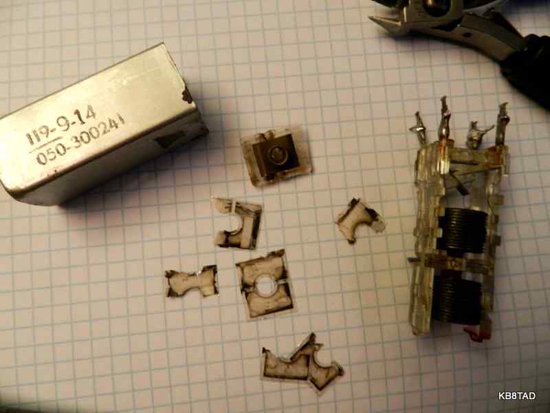
Replacing the Silver micas
In checking for a probable capacitor size to mount outside the can to replace the silver micas that had been removed, I noticed websites mentioning 100 pF. I tried that. The IFs would not peak any better than before. Frustrated, I decided to simply mount two compression trimmers on the first IF. I preset the compression trimmers to 100 pF and backed the internal ferrite slugs off a couple of turns.
That did it! I turned the compression trimmers somewhat and noticed a tremendous rise in noise. For all this time, I had turned the sensitivity control all the way up. Thinking something was wrong, I took me a moment to realize that the noise was stage gain! Turning down the sensitivity control and minimizing the 455 KHz source from the signal generator, I peaked the input IF to a very sharp point on both sides of the transformer. Removing one of the compression trimmers, I found that it was adjusted to about 300 pF. Replacing it with a fixed cap of that value allowed a nice peak adjustment. It was no wonder that the earlier 100 pF cap would not allow me to peak the IF. I repaired the next IF in the same manner.
The BFO
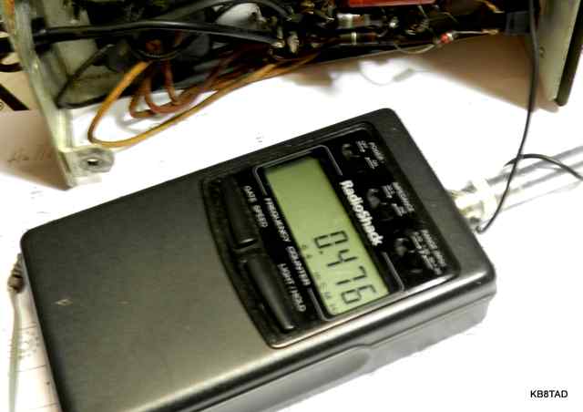
The next task was tackling the non-working BFO. It turned out to be an easy fix. A scope check at the 12AX7 grid confirmed that the oscillator was working. A wire from the grid is wrapped and glued around a terminal of the 6AL5 tube socket. That wire makes for a small capacitance to inject the BFO signal. Connecting a clip lead to the grid terminal and wrapping it around the antenna probe of my frequency counter confirmed that the BFO was working but at 476 KHz, not 455. No wonder I could not hear it.
So what had happened to the set? I'm assuming that the silver mica disease had progressed to where the caps had deteriorated to much reduced capacitance. It's likely that the noise and crackling symptoms usually associated with silver-mica disease may have occurred much earlier in the set's life.
I followed up with a complete RF alignment. The set was now capable of hearing those same two local stations with no antenna connected and the sensitivity control turned all the way down, a tremendous difference.
Performance
In fact, the set was almost too sensitive. That double IF stage really makes a difference. As others have noticed with a properly functioning S-107, the AGC can be readily overwhelmed with a strong signal. The sensitivity control must be backed down to avoid audio distortion. But nearly any weak signal can be easily heard. With just a hank of wire for an antenna, the S-107 rivals my GE Superadio on the broadcast band. It is also great for short wave listening. With that same hank of wire, I listened to several SSB conversations on 80 and 40 meters with the volume control up while riding the sensitivity control for best sound. I was developing a growing fondness for this little set. The fondness is partly due to the satisfaction of rescuing the set from awful performance to the top of its capability.
I had been listening to the set with an external speaker. Removing the set's speaker revealed it to be in poor condition. I installed a matching 4 by 6 inch speaker from the over-stocked "boxe de junque".
More info on replacing IF caps suffering silver migration
For more information on replacing the silver mica caps in an IF transformer that appears to be almost identical to those in the S-107, see this link.
More Hallicrafters
I have repaired and documented other Hallicrafter radios.
A list and links to those Hallicrafter radios can be found here.
Manual source
A manual, schematic, and dial stringing diagram for the S-107 can be found on BAMA. Click here for a link to manual sources and BAMA.
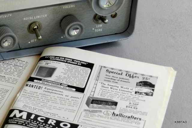
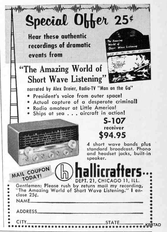
Hallicrafters 1959 ad in Popular Electronics --- $94.95 for the S-107 and 25 cents for a shortwave record
Hallicrafters encouraged shortwave listening by offering a 45 RPM record of shortwave transmissions for 25 cents in 1959. That record now goes for silly prices on online auction sites but
has been recorded on Youtube. Click on the ad below to listen.
Date 8-28-12
An Unknown Regenerative Receiver was the previous item on the bench.