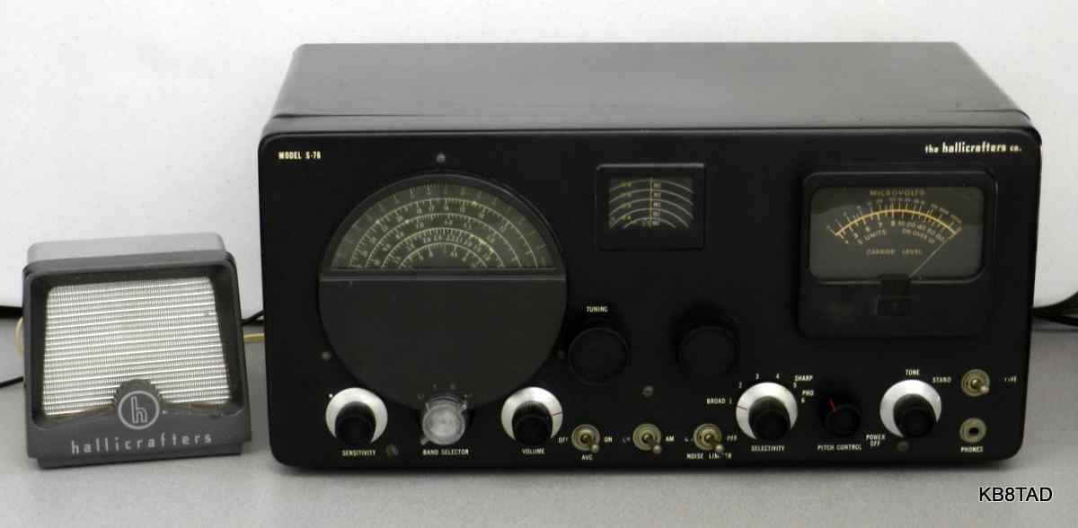
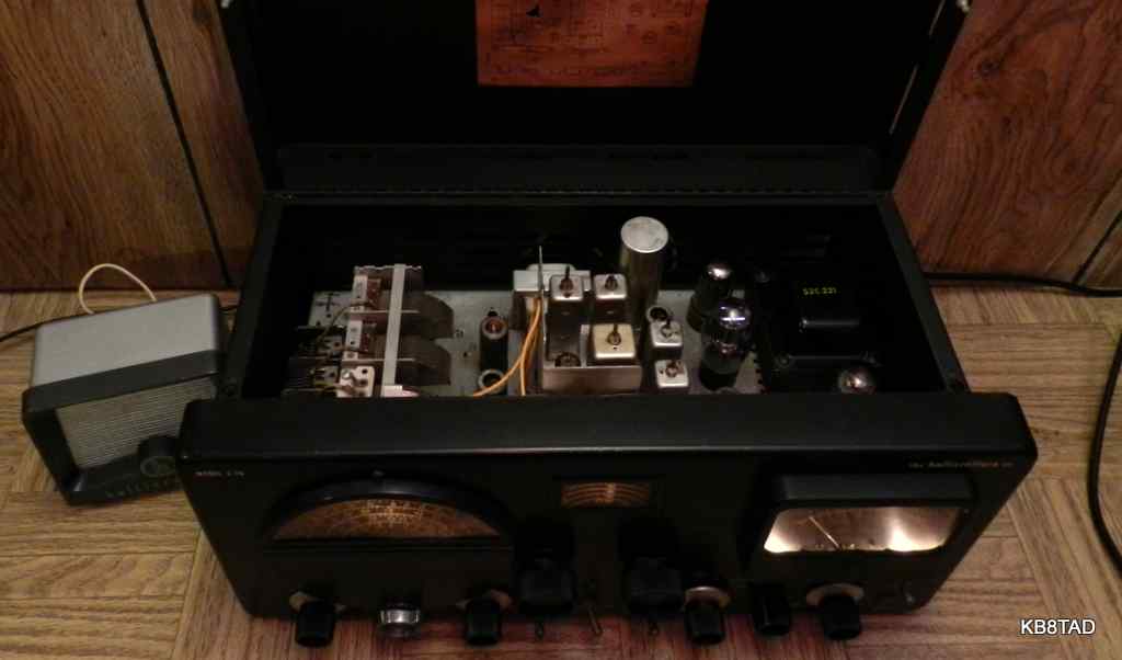
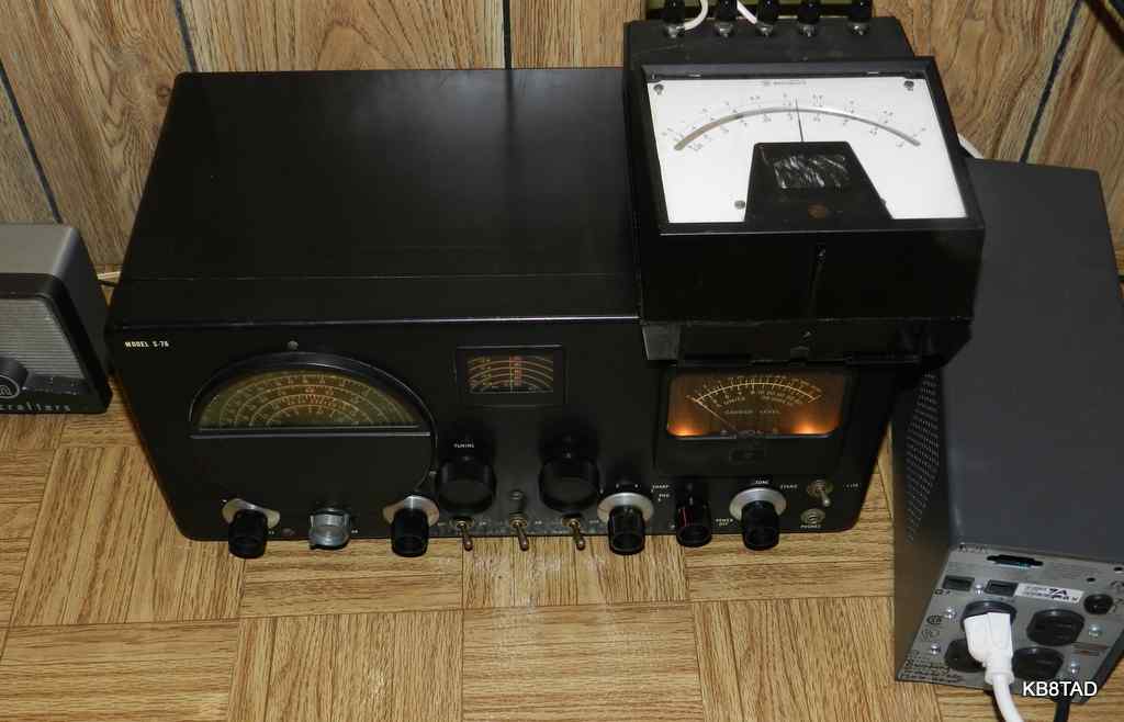
The S-76 is a 4 band dual conversion communications receiver covering AM broadcast and shortwave from 538 to 1580 KHz and from 1720 KHz to 32 MHz. IFs are 1650 KHz and 50 KHz. The 1650 KHz IF accounts for the gap in coverage between 1580 and 1720 KHz. The bandspread is calibrated for the 80, 40, 20, 11, and 10 meter ham bands with the 15 meter band added later after that band became available to hams. This example includes the 15 meter bandspread.
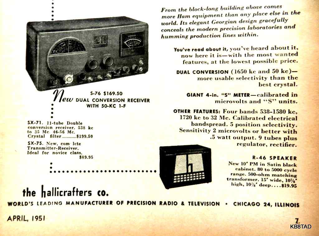
The set requires an external speaker. Hallicrafters recommended the R-46, the same as for the SX-71. Not having an R-46, I subbed an R-47. Tube complement for the S-76 is 6CB6 for RF amp, a 6AU6 as 1650 KHz mixer, 6C4 for oscillator, a pair of 6BA6, one for each of the two IF amps, a 6BE6 for the 50 KHz converter, a 6AL5 for detector, AVC, and noise limiter, a 6SC7 as audio amp and BFO, a 6K6GT as audio output, a VR-150/0D3 as voltage regulator, and a 5Y3GT rectifier.
When compared with the SX-71, the S-76 loses 2 tubes as well as the 6 meter band, narrow-band FM, and crystal filtering/ phasing for the $30 saving. This reduced capability was apparent to hams. Therefore the SX-71 is more prevalent today than the lower cost S-76 which has been labeled as "scarce" by Osterman in his book "Shortwave Receivers Past and Present". He labels the SX-71 as "common".
Starting Repairs
This S-76 was in decent cosmetic condition as purchased although in need of a thorough cleaning. The glass was loose inside the S-meter.
A series of initial checks and unpowered testing
As with any radio, I first do continuity checks on the line plug to determine if the power switch, fuse (if any) and power transformer primary are intact. I know roughly what to look for in terms of transformer winding resistance on my Triplett 630A "work-horse" VOM.
The power switch most often needs a bit of deoxit to make good contact. This radio was no exception. However, I found a hard short between the power plug and the chassis. Was the transformer the problem? I cut out the micamold cap which was connected on a terminal strip between one side of the power line and the chassis. The short was now gone. The micamold power line cap was not just leaky but a hard short circuit. Had that short encouraged the prior owner to sell it quickly when he felt voltage on the chassis? Perhaps.
I also noticed a tube substitution. The 5Y3 rectifier had been replaced by a 5Z4, a metal tube. That was a reasonable substitution voltage and current-wise,.. but wait. A metal tube connects pin 1 to its metal shell. A quick check showed that Hallicrafters had used pin 1 of the rectifier socket as a B+ tie point. Therefore the tube shell would be live with B+, a "gotcha" just waiting for the unwary. I quickly located a proper glass 5Y3GT.
As expected, the toggle switches were open and, as usual, the switches were successfully repaired by applying Deoxit at the base of the bat handles while the chassis was on its back, switches pointing up, letting gravity help. And as usual, I used a bit of contact cleaner sparingly on the bandswitch and the other controls.
I connected a speaker and tested the unpowered set with the ohmmeter on low range connected between B+ and the plate connection of the audio output tube. That check tells me whether the output transformer and speaker connections are good. I heard the scratchy noise in the speaker telling me the signal path from output tube to speaker was intact.
A this stage, I replaced the power cord with a three-wire grounded one recycled from a computer. I connected a new cap in place of the shorted micamold but wired it from chassis to the neutral connection (white wire in the power cord) which was wired directly to the power transformer. The line side was wired to the power switch. If I were adding an in-line fuse, I would place it between the line in (black wire on the power cord) and the power switch. And yes, I always check to make sure that the white and black wires are correctly placed in these foreign-made cords. I also sometimes find power cords which are the European standard of brown for line and blue for neutral.
A final check with the ohmmeter is from chassis to the main B+ line to determine if there is sufficient resistance. If I find less than about 30,000 ohms, I check to see why. Typically the electrolytics will charge somewhat from my ohmmeter's battery on high range and the resistance will swing upwards to several hundred thousand ohms. The battery on my Triplett 630A on its highest ohmmeter range is 30 volts. The ohmmeter charging action gives me a good early indication that the electrolytics will probably reform.
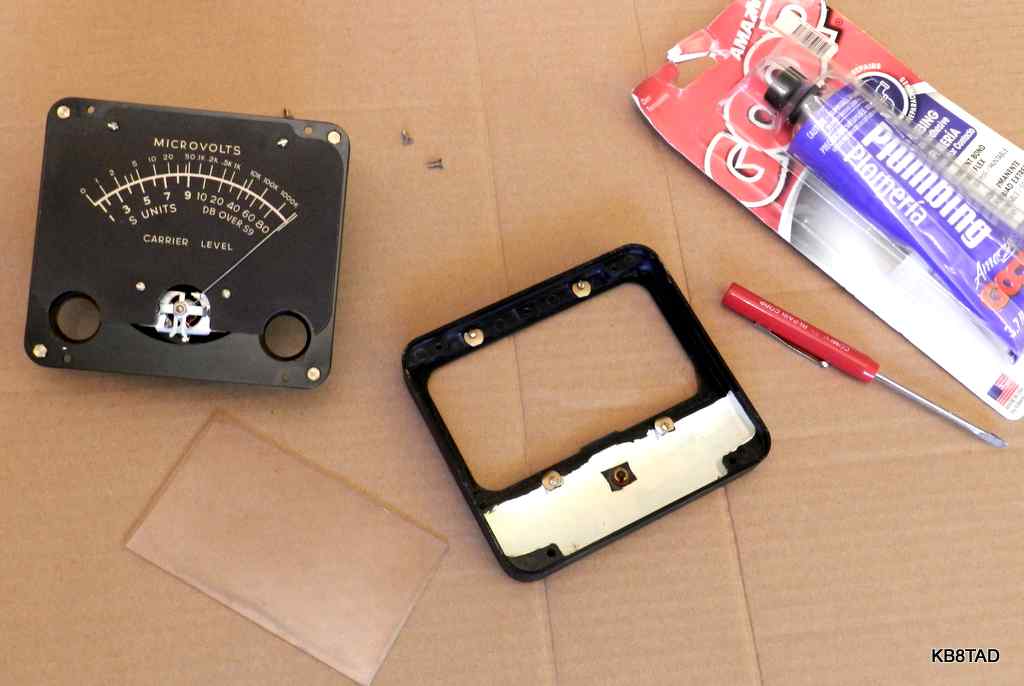
Repair and testing of the S-meter
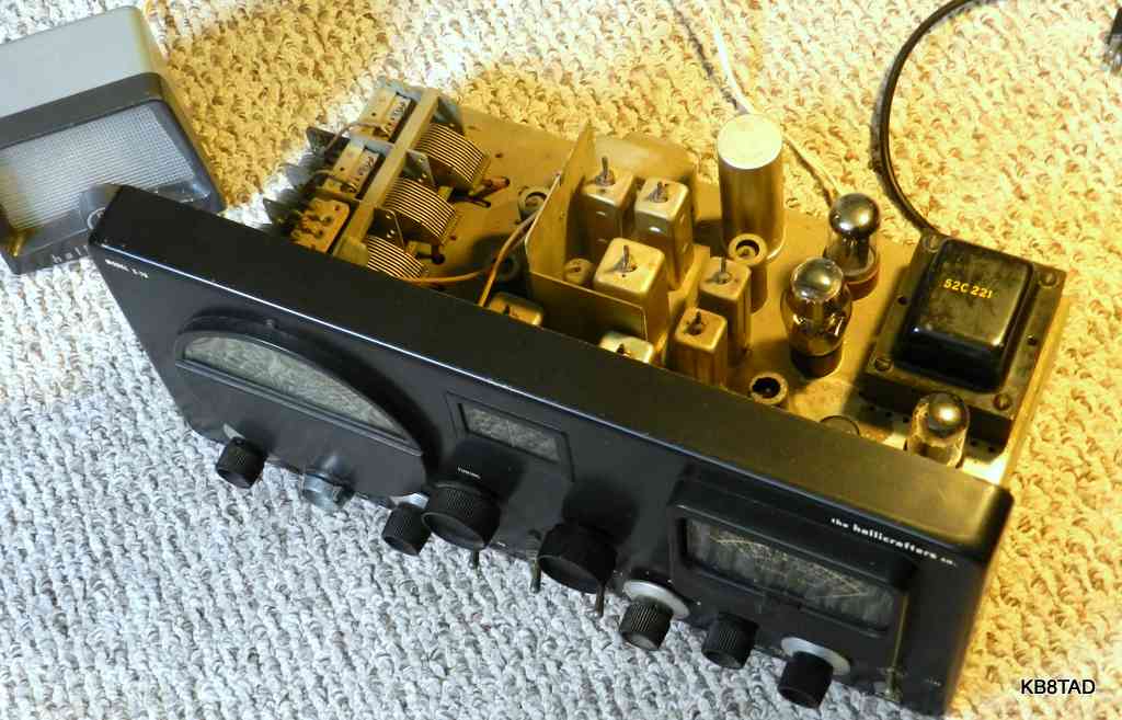
The Hallicrafters ads emphasize the large 4 inch S-meter in the S-76. Mine had the crystal face loose which interfered with the pointer. I removed the meter and opened it.
(update: 4-10-14)
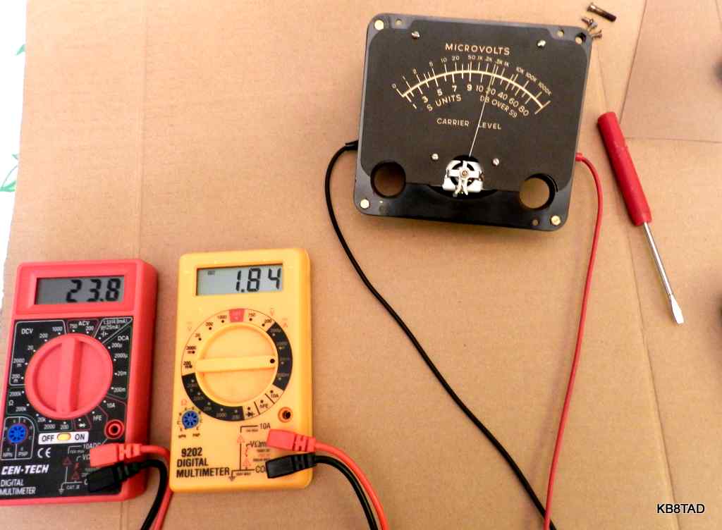
I tested the S-meter movement using the ohmmeter function of my cheap Harbor Freight digital meter.
Tentative conclusions on the Run differences for the S-76.
Run 1 , as shown in the Sams Photofact, has no 15 meter bandspread scale and also has knobs with no metal skirts. At some point early in Run 1, Hallicrafters changed the bandswitch knob from one that resembles the other knobs to a more substantial bright metal knob.
Run 2 has the bright metal knob skirts and can be found either with the 15 meter bandspread scale or, earlier ones, without the 15 meter scale. Knob markings are in red and white. The Hallicrafters name and the model are in green.
Run 3 continues the bright metal knob skirts and the 15 meter scale but all front panel markings are in white. Run 3 has a round "Listed Under Reexamination service" UL sticker between the phono jack and the S-meter control.
By comparing the alignment information and the schematics I have not yet found any major electrical differences between the Run series.
Note that this is a working list and is subject to updating and changes as more information is available. The interesting note thus far is that the Run 2 can be found with either the four or the five bandspread scales (the added 15 meter band) which makes me wonder if there are unique chassis markings about that change. Let me know if you have information to add to or correct this tentative list.
(update: 4-23-14)
Replacing capacitors
In every radio, some, most or all of the capacitors need to be replaced. Ceramic disc and mica capacitors seldom fail. I normally do not replace those unless there is a circuit fault.
Critical capacitors
I automatically replace the one or two line capacitors in the set for safety and also the audio coupling capacitor to the input grid of the audio output tube since leakage can upset the bias. The resulting overload can take out the output transformer and possibly the power transformer if the transformer is marginal, near its saturation limit.
Other capacitors
The AVC circuit capacitors are normally also replaced since leakage in the high impedance AVC line can seriously affect the AVC action and cause distortion. Lastly, I usually replace caps that see high voltage such as the screen grid caps. The few caps that are left are typically the cathode bypass caps which are low voltage and low impedance. Those seldom need replacement. I followed that procedure again with this radio. Surprisingly the removed caps all tested at relatively low leakage. All of the 0.005 caps in the screen grid circuits were ceramic and did not need to be replaced.
Initial power up
I typically power the radio with my isolated variac after replacing just the critical caps, watching current draw and voltage very carefully. The set came to life with decent sensitivity. After replacing the other capacitors as noted, I powered it again. I was pleased with the performance even before alignment. I had removed the BFO knob so the oscillator coil could be adjusted for picking up SSB signals. I listened to several 80 meter SSB conversations with just a hank of wire for antenna.
(update: 5-13-14)
Difficulties with Alignment of the 50 KHz IF chain
I wanted maximum performance and that meant alignment. The alignment instructions note that a 50 KHz unmodulated source is needed for the second IF chain. That frequency is not typically available in general purpose RF signal generators. The instructions also suggest an alternate, using a pair of signal generators, one at 700 KHz and another at 750 KHz and using the 50 KHz mix difference for the alignment source.
I decided to use my Precision E-310B function generator that covers from 20 Hz to 2 MHz since only an unmodulated signal was required. I followed the alignment directions but was not successful using the instructions as written in the manual. I found out why by using a scope to monitor the 50 KHz signal at the input point, terminal 1 of transformer T2. It turned out that input at that point largely shorted out the signal and fed back the 1600 KHz oscillator signal. I decide to pull the 6BE6 used as the 1600 KHz oscillator and mixer and feed a signal to pin 5 of the 6BE6 tube socket through a small dipped mica cap. I used a Pomona socket extender to connect to pin 5.
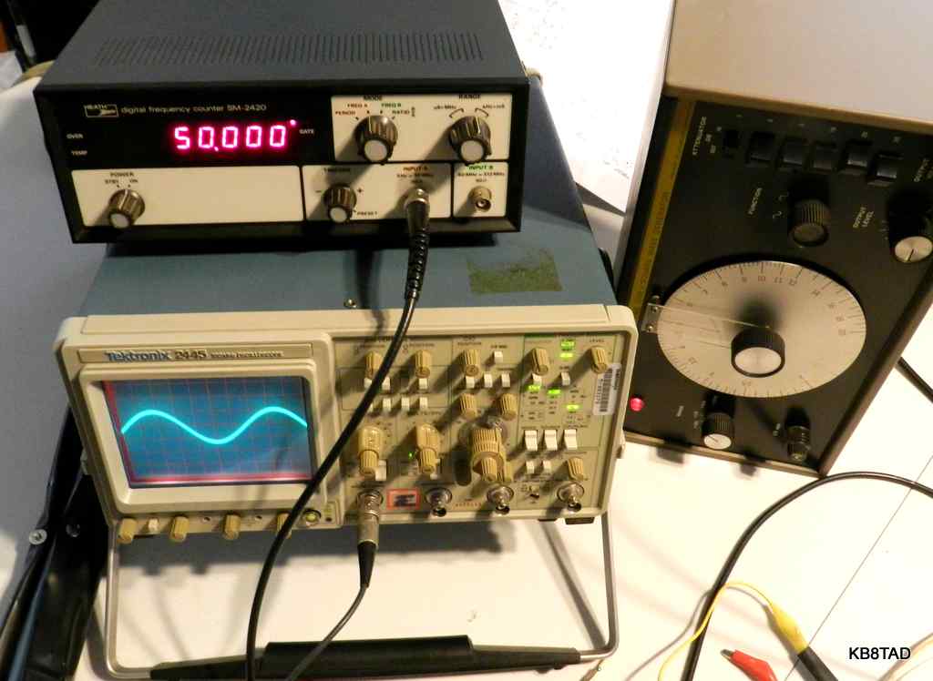
Rather than using the DC voltage of the detector tube plate as the measuring point as described in the instructions, I used a low capacitance scope probe on the cathode side of the detector tube. That did the trick and I was able to observe the actual 50 KHz signal. The scope showed a nice increase and peak as I tweaked the 50 KHz IF transformers. As necessary, I reduced the gain of the generator to a minimum. For the final adjustments, I disconnected the input clip to the function generator, leaving the clip near to the generator output lead, just using a bit of stray capacitance for the 50 KHz input.
Knowing I had the second IF at exactly 50 KHz, I used a quick method of setting the 1600 KHz oscillator. I monitored a local broadcast station at the radio's most selective setting and tweaked the oscillator so that the oscillator signal at the tuning cap was exactly 1650 KHz higher as read on my frequency counter.
Simplified RF alignment with a frequency counter.
The alignment instructions note that the oscillator operates on the high side for all of the bands. With the IFs aligned accurately, I used the frequency counter to adjust the oscillator settings for the high and low ends of each of the four bands at the frequencies noted in the alignment instructions, setting each oscillator point at 1650 KHz higher than the tuned frequency. This enabled me to quickly move back and forth to the designated high and low settings on each band since the high and low settings interact somewhat. After several back and forth high and low adjustments, the oscillator settings were correct for each end of the band. The RF adjustments for each band were made using a standard RF signal generator, but I could also simply have aligned those trimmers using band noise. I found that the peaks for RF and for maximum noise were identical.
While the set seemed to be working well before alignment, full alignment made a major difference in sensitivity.
Power Draw
After about 45 minutes of operation, I noticed that the power transformer was quite warm, although not too hot to touch. I decided that since my line voltage was over 120 at times, I needed a solution that would lower the line voltage for the radio. The Sams Photofact for the set notes a power draw of 0.71 amp at 117 volts. I measured 0.72 amp at 120 volts with the RF gain at maximum. While the set was operating as designed, I prefer to run these older radios at a bit less power using either a variac or a bucking transformer.
Making a cheap bucking transformer
I had picked up a couple of defunct uninterruptible power supplies (UPS) designed for computers from the local recycle/ re-use store at $2 each. I look for UPS cast-offs that are moderate in size but are still a bit heavy after removing the usually dead rechargeable battery. That weight is due to the transformer inside the UPS which is ideal for converting that UPS into a bucking transformer system. The transformer inside typically is capable of stepping down 120 line voltage to 10 or 12 volts or so. I remove the UPS circuit board and rewire just the transformer as needed while also re-using the power outlets, power switch, fuse and case. The line voltage at the output was reduced by the 12 volt transformer winding resulting in an output of about 110 volts, ideal for powering a vintage radio such as this Hallicrafters. The circuit for a bucking transformer is easy to find on the web. I have not included it here. If you need help in creating one, please check with a local mentor for safety. Check the output voltage to make sure that the voltage is reduced rather than increased. If miswired such that it increases the voltage, swap the 12 volt connection wires. Note that a bucking transformer does not provide isolation.
The bucking transformer from my converted UPS reduced the voltage to 110. The S-76 drew only 0.62 amp at that voltage, a reduction of 0.1 amp, with no noticeable loss of performance.
Performance
Although it has fewer features than the SX-71, the S-76 did not disappoint me. The 50 KHz second IF chain and the multiple selectivity settings are ideal both for general shortwave listening and for reducing adjacent signals on the ham bands. It is a capable receiver and that big S-meter is unique and fun to watch. It will outperform the typical 455 KHz IF single conversion sets at the higher frequencies. The R-47 speaker shown is a match for later Hallicrafters radios such as the SX-130. The speaker is designed for voice frequencies and works well with the S-76.
(updated 5-23-14)
Manual sources
A manual for the S-76 in DJVU format and a Sams Photofact in PDF,
can be found on BAMA
A very good PDF copy of the Run 3 manual for the S-76 can be found at this link.
Here is a PDF copy of the S-76 manual (Run 1) from Julian Bunn.
Here
is Julian's S-76 page with more information and pictures.
More Hallicrafters sets
I have repaired and documented other Hallicrafters radios.
A list and links to those Hallicrafter radios can be found here.
An article on Ground Fault Protection and the AC-DC radio was the previous project "on the bench".