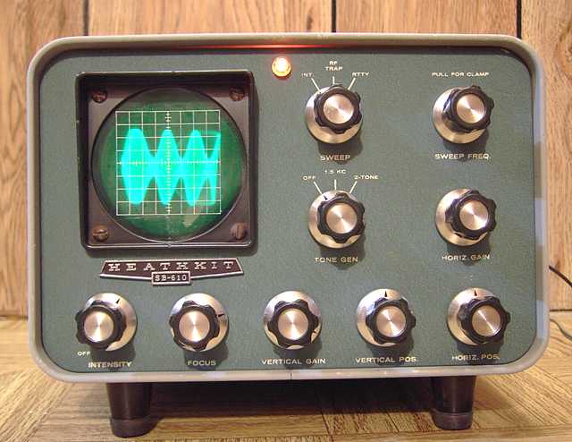
Heath SB-610 showing display from a modulated RF signal generator at 3000 KHz.
Modulation is about 50%. The real-time scope image is bright and very sharp but
the half-second exposure time softens the photo image somewhat.
The SB-610 is a display to monitor "on the air" signals. The manual notes that the unit can be used from 160 to 6 meters without tuning or modification. Its primary purpose is monitoring the transmitted signal pattern; the RF envelope, RF trapezoid, or RTTY cross pattern. A rear-panel attenuator can accommodate any transmitter from 15 watts to 1 kilowatt. The SB-610 can also monitor the other station's signal when connected to a receiver's final IF amplifier stage, assuming the receiver IF has sufficient bandwidth. This unit came equipped with 3000-6000 KHz coils to match the 3395 KHz IF of Heathkit's SB-line and HW-100 series. Monitoring for another IF such as 455 KHz would require substituting the proper coil in the vertical amp plate circuit. Heath originally provided such coils along with instructions in the manual. I suspect that a simple IF transformer primary for a high impedance tube circuit would work fine as a substitute for the plate coil.
Repairs and testing
After safety checks including making sure the proper fuse was installed, I applied partial AC voltage with a variac while monitoring the B+, the AC current draw, and the critical CRT (cathode ray tube) high voltage circuit.
The CRT requires a high voltage of -1430 in this circuit. Problems with the CRT high voltage are common for the SB-610. Note that the circuits in boatanchor radios use dangerous voltages. This is especially true of a monitor/ oscilloscope. Troubleshooting and repair should be done carefully by someone with the requisite skills.
CRT high voltage problem
The B+ circuit was fine but the CRT high voltage was less than half of what was expected. There was no green spot or light on the CRT. I checked the power transformer and was relieved to find that the 600 VAC winding that feeds the CRT high voltage was intact. A quick check of the filter capacitors showed a shorted 0.15 MFD cap. That cap was supposed to be rated for 1600 volts, but apparently a former repairman had substituted a 600 volt cap, dooming it to quick failure. With a shorted cap but a good transformer, I immediately suspected the high voltage rectifiers. I learned that while those rectifiers look like large silicon diodes, Heath identifies them as selenium rectifiers. The one was open and the other suspect. I was not able to determine the original PIV (peak inverse voltage) or current ratings of those rectifiers. However, the circuit is a straight-forward doubler. I decided to replace each with four 1N4007 silicon rectifiers in series. Each 1N4007 has a rated PIV of 1000 volts. I used heat-shrink tubing on the series diodes leaving the body of the end diode partially exposed so I could see the cathode marking. Before installing the diodes, I checked the circuit for any further evidence of former repair. I found that a 330K ohm resistor had been replaced by a 1 K ohm, probably in an unsuccessful attempt to increase the low voltage. I replaced the rectifiers, the caps, and the missing 330K resistor and followed up by testing to make sure the CRT high voltage was working properly.
Focus problem
The CRT now had plenty of voltage and showed a green line although it could not be focused properly. The resistor between ground and the focus control had increased in value. Replacing it solved the focus problem.
Lacking a receiver with 3000 KHz IF, I used a signal generator to feed the vertical circuit. A satisfying display appeared around 3000 KHz. I could peak it at that frequency or higher by adjusting the coils. Varying the modulation level of the signal generator brought a nice pattern on the monitor as shown above. Connecting it to a known-good transmitter produced the classic trapezoid pattern.
Tone generator problem
The SB-610 has an onboard two-tone generator providing for 1500 and 1950 Hz sine-wave audio signals fed to an RCA jack for output for testing SSB tranceivers. I fed the output to a scope and found a very low level signal, well below the nominal 50 millivolts Heath intended. Probing the circuit with the scope revealed that the chassis mounted level control was open. Application of contact cleaner did not solve the problem. I replaced the control with a better quality unit from the boxe de junque.
Cosmetics
While the front panel and chassis of the SB-610 cleaned up very nicely, the case was in need of paint. I sprayed it with acrylic paint that was computer matched by the local Sherwin-Williams paint store. (No connection other than satisfied customer.)
The SB-610 is proving to be a handy unit for monitoring transmitter output quality, a nice tool in the ham shack.
11-07
Repairing a series of Signal Tracers with crystal diodes in the probe was the previous project on the bench.