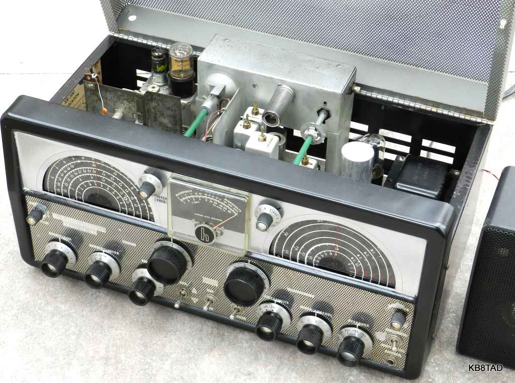
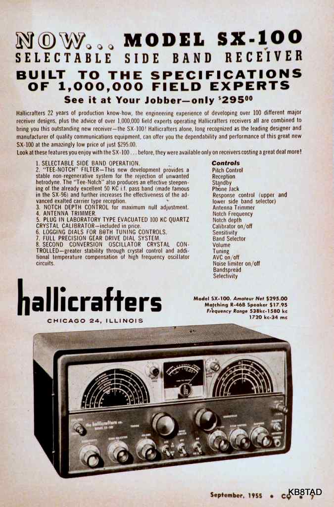
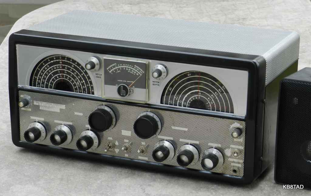
Hallicrafters SX-100 receiver

The Hallicrafters SX-100 is a 14 tube set covering the broadcast band from 538 to 1580 KHz and three short wave bands from 1720 KHz to 34 MHz. The gap from 1580 to 1720 KHz is there because the receiver first IF is 1650 KHz. The second conversion is crystal-controlled for an IF of 50.5 or 50.75 KHz. Bandspread is calibrated for the 80, 40, 20, 15 and 11-10 meter ham bands. The set was reviewed in QST magazine in December 1955.
This example is a Mark II version according to the stamp on the back of the upper module. Other versions include Mark I, Mark IA, Mark IB, Mark IIA, and Mark IIB. The differences are primarily cosmetic such as knob style but there are also electronic differences. The major electronic differences are a change to 50.75 KHz for the Mark II series 2nd IF chain versus 50.5 KHz for the earlier Mark I series and a Mark II change that increased the AVC delay when switched to SSB/CW (details below).
Condition
As purchased, this radio was non-operative, in poor cosmetics and in need of paint, but the hamfest price was in accord with the condition.
Repairs
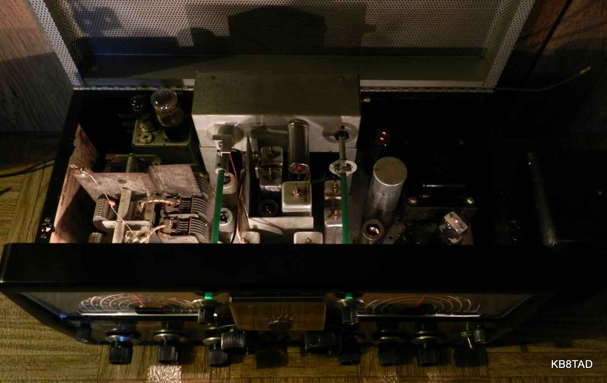
After unpowered safety checks, I connected a speaker and powered the set slowly. I checked the grid bias on the 6K6 output tube and found a positive voltage on the input grid. I shut the set off quickly and replaced all three capacitors that are part of the grid input circuit as selected by the "response" control. There was still no sound from the radio. I checked the audio stages by switching to the phono input and touching a screwdriver to the phono jack. A satisfying hum level indicated the audio stages were working.
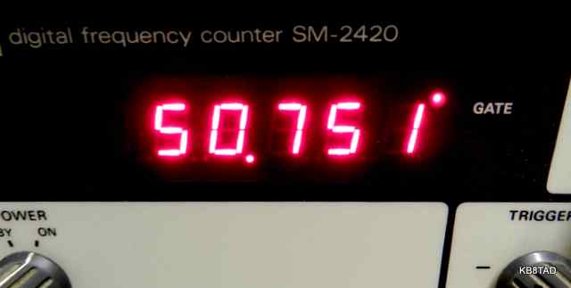
The set has two IF chains. I next checked the main oscillator with a frequency counter to make sure it was operative. I found a strong signal that was nominally 1650 KHz above the tuned frequency.
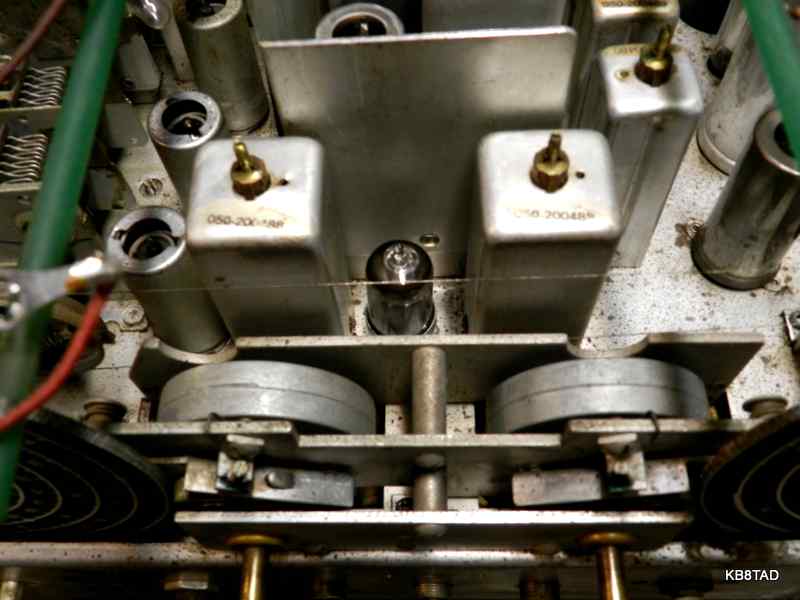
The second converter with its 1600 and 1700 KHz crystal oscillators and part of the second IF chain is mostly located on a separate sub-chassis that is very difficult to access and service. I was wondering if any signal was being passed by that stage. Were the crystals good and oscillator functioning? Could the 50.75 KHz IF chain pass a signal? My signal generator was not capable of going down to 50 KHz for any type of test.
Tracing the signal
My next step was to use a signal tracer to trace the signal in the first conversion IF to see if the signal was getting to that hard-to-access second conversion sub-chassis. It's there that I discovered the signal loss at the 6BA6 first IF amp. The signal got as far as the input grid but not at the plate of that tube which feeds the second IF transformer just ahead of the coax to the second conversion subchassis. The screen voltage was fine. The tube tested weak but not dead. I replaced both that tube as well as another 6BA6 that tested as weak. No change.
I noticed that all the tube sockets including the one where the signal was lost were designed with a bump in the center that limits the reach of the tube pins. I applied deoxit to all the sockets and used a brass-bristle brush on the tube pins. That finally resulted in a signal that moved the S-meter and passed the signal to the plate of the new 6BA6. However, tube contact was somewhat intermittent and I still could not get any sound out of the radio.
Pomona tube extenders
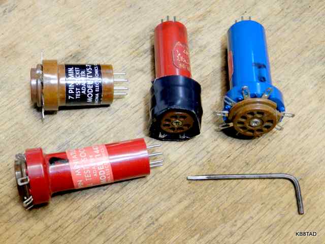
I finally decided to check the second conversion subchassis. Were the crystal oscillators (1600 KHz and 1700 KHz) working? There is no direct access to the tube socket connections or subchassis circuitry. I used my Pomona socket extenders, carefully bending the upper contact ears inward and wrapping them with a layer of tape to prevent shorts since the subchassis is very compact with IF and oscillator transformer shields very close to the tubes. I also used a Pomona extender on that flaky socket with the 6BA6 first IF tube since the extender contact pins go deeper than that of a typical tube. That stabilized the signal from that tube. I also heard the first signs of life in the radio, but it was intermittent.
Checking with the scope
Checking the 1600 and 1700 KHz oscillators at the grids of the 12AT7 by way of a Pomona extender showed plenty of signal on the oscilloscope. The crystal oscillators were working well. I also checked the signal at the second converter with the scope and noticed that if I turned the SX-100 sensitivity control down, both the first IF carrier and the oscillator in the mixed signal decreased in level slowly as expected but at the weakest sensitivity setting, the carrier disappeared and the oscillator signal suddenly increased in intensity. All the while, the radio occasionally worked but then dropped out even with the sensitivity at maximum. The sound was also distorted. There had to be another problem. Was it another case of the tube pins not touching properly?
More signal tracing
I again used the signal tracer, this time on the 50.75 IF chain. The signal was there at each point, all the way to the detector, then the audio preamp and surprisingly, right up to the 6K6 audio output tube. Then nothing. I quickly checked voltages. The audio output transformer which I had checked in the beginning was now open! It had apparently become intermittent while I was testing the set and had now fully opened. I suspect that it had been run with the 6K6 leaky capacitor bias problem for quite some time before I obtained the set. I found a universal replacement in the "boxe de junque" that fit the original metal shells and housing. The replacement worked well. It had the standard speaker low impedance output but not the extra 500 ohm secondary. I could live with that. The set was working and the distortion was now cleared up. However, that problem 6BA6 tube socket remained a problem.
Replacing the socket
With the Pomona socket extender now removed, the 6BA6 needed to be pulled to one side to make adequate contact. More deoxit did not help. There was little choice but replacing the socket. I pulled all the socket connections after diagramming them on paper and taking a couple of pictures of the connections. I then used a Dremel tool with a flex-shaft extension and a tiny rotary grind stone to grind off the socket rivets in the very confined space. That was followed by mounting a NOS replacement socket with small screws.
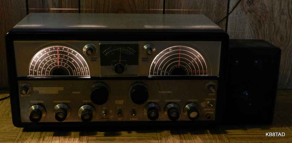
With the set now functional, I replaced most of the remaining caps. I also cleaned and checked the crystal calibrator, observing its signal with the scope. That completed repairs. The set was then given some badly-needed paint.
Alignment
Alignment of this set is not the simplest but the step-by-step procedure is detailed in the manual. A stable source of 50.5 or 50.75 KHz signal is required. However, since the output is measured at the detector by a VTVM, modulation is not necessary. I was again able to use my function generator. The 1600 and 1700 KHz "crystal activity adjustments" are somewhat critical. The signal can totally disappear if the level of activity is adjusted a bit too high. Receiver sensitivity is reduced if activity is too low. A mis-adjusted activity level can totally block the signal. That explained what I had observed with my scope connected to the second mixer as the RF sensitivity control was reduced to near minimum and suddenly the oscillator output level at the mixer seemed to jump up resulting in loss of signal.
Unusual tools
for Tubes in tight places
Because of the chassis crowding, the tubes in the second converter subchassis and the 6BA6 in the replaced socket are difficult to remove and replace. Not having a tube puller, I used a piece of electrical tape stuck on the tube to pull it up while wiggling it side to side. To replace the tube, I used the same scheme but put the tape on both sides of the tube as a handle placed so that I knew exactly where the space in the pins was and could set the tube properly over the socket and then press down gently. Once the tube was in place, I peeled the tape off.
A square Allen wrench?
In removing the front panel, all the larger knobs use standard hex set screws and can be removed with the proper Allen wrench. However, the smaller knobs were fastened by set screws with small square openings rather than the standard hex set screws. Not having the right tool, I used the Dremel grinder to fashion a square-headed tool out of a spare Allen wrench. (pictured above with the Pomona socket extenders).
Performance
After repairs and alignment, the SX-100 did not disappoint me. The set is every bit as sensitive and selective as expected for a top-of-the line set in its era. I listened to a variety of SSB conversations on 80 and 40 meters with just a hank of wire for an antenna. The notch filter was effective at slicing out an interfering heterodyne. With my 80 meter dipole attached and some proper warm-up, it held its own against my Kenwood TS-850/AT on the lower frequency ham bands. I had heard that stability was poor due to mechanical weakness. I tried thumping the set while listening to SSB but found that the set was actually very stable and relatively immune to mechanical vibration. I'm wondering if a worn tube socket with poor contacts might have caused the instability problems experienced by some owners.
On the broadcast band, the set exhibited excellent sensitivity and selectivity although the maximum bandwidth is 5 KHz, obviously not hi-fi. But that relatively narrow bandwidth enabled listening to distant stations very close to a local broadcaster that would bleed over and wipe out those stations on a lesser radio. The handy antenna tuning control helped especially on the broadcast band where the antenna match at the high end and low end of the band are considerably different.
Upgrading the AVC of a Mark I to the Mark II
In comparing the two schematics (Ia versus II, both manuals are on BAMA), the following changes were made with the Mark II. The AVC of a Mark I set can easily be upgraded to Mark II with those changes.
Resistors R-46 and R-47 were removed. The AVC cathode (pin 9 of the 6BJ7) is grounded. The 300 pF BFO injection capacitor (C-93) is moved from the 6SC7 grid (pin 3) to its plate (pin 2).
The AM /SSB switch that was a single pole (SPST) is replaced with a double pole (DPST) switch. One half of the DPST switch is connected just as in the Mark I set to turn on the B+ for the BFO but the second half switches to ground one side of a new 0.5 MFD capacitor (C112) which is wired in parallel on the AVC line with the existing 0.047 MFD capacitor (C77). The new capacitor, with its one side switched to ground, slows the AVC.
More Hallicrafters
I have repaired and documented other Hallicrafter radios.
A list and links to those Hallicrafter radios can be found here.
Manual source
The Mark Ia and Mark II manuals can be found on BAMA in djvu format. Click here for a link to manual sources and BAMA.
Date 10-22-12
A Motorola HS-701A audio amp was the previous item on the bench.