Hallicrafters SX-17
the "Special Model" Super Skyrider
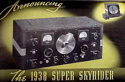
In 1937, Hallicrafters introduced the "new 1938 Super Skyrider", the SX-16 (pictured in the June 1937 QST ad below). Apparently, to meet a special order, Hallicrafters made a variation of that Super Skyrider in late 1937 / early 1938. In the March 1938 QST full page ad, Hallicrafters has a side-bar note:
The April full page ad notes:
"By Popular Request the SX17. A SPECIAL MODEL SUPER SKYRIDER
The ad notes,
It was not our intention to include this special receiver in the regular Hallicrafters line. However, without formal announcement of any kind, the news about the SX-17 spread as its owners talked about it over the air and to their friends. To our amazement, we found ourselves deluged with inquiries and orders.
With such a situation, and with the Hallicrafters policy of building what the amateur wants, we have no choice but to include the SX17 in our line. Here it is.
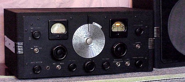
The SX-17 has an added noise limiter switch on the front panel in the lower right corner. Otherwise, the SX-16 and SX-17 have identical front panels. The SX-16 is reviewed in two separate articles in Radio News by Laurence Cockaday and Gordon Taylor in November 1937 (page 280, Has schematic and technical info including lab measurement of useful sensitivity) and December 1937 (on air testing). They note that the upper band is primarily useful only for local comunication.
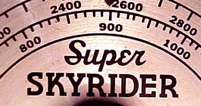
The SX-17 has 13 tubes compared to the SX-16 with 11. The extra 2 tubes are the added 6K7 second RF stage and the 6H6 noise limiter. (An early version uses a 6J5 for the noise limiter.) Coverage for both models is from 540 KHz to 62 MHz in 6 bands. The upper band does not use the RF amp. Price for the SX-16 was $111 with crystal. Price for the SX-17 was 137.50 with crystal and $149.50 with the optional speaker. The "meter" to the right of center is the electrical bandspread scale which was advertised at "1000 degrees" (almost three rotations). The portion of the bandspread scale in use is highlighted with a moving pilot light, shown in the picture as a bright spot.
The "X" in the model indicates the crystal filter. These sets were also sold as the S-16 and S-17 without the crystal filter. The speaker sold with both models is the 12 inch R-12T (which accompanied this sample). The speaker includes a 5000 ohm matching transformer. There is also an 8 inch speaker, the R-8T.
It is believed that the "special order" refers to a model built for the FCC (Federal Communications Commission) which required the extra RF stage and the noise limiter. That model also has a front-panel switch for selecting either 117 AC or mobile power from a 6 volt storage battery using an external vibrator pack. A front panel control for zeroing the S-meter was also included. The FCC model has single-ended audio (just one 6V6) which I assume was to reduce the power requirement in mobile use. I am assuming that the SX-17 is the logical result of that special order. The FCC model is specially marked and the model number is SX-17F.
The "Skyrider" name.
The first Hallicrafters set, the S-1, came with the imaginative name of "Skyrider" Several early Skyriders were regenerative sets. The "Super" was added with the introduction of the first Hallicrafters superheterodyne model, the S-4/ SX-4. The name "Super Skyrider" still evokes that magic feeling of the mystery and exotic on the shortwaves. The SX-28A was the last Hallicrafters receiver to use the "Super Skyrider" name. The last Hallicrafters sets to use Skyrider as part of the name were the S-41 Skyrider Jr. receiver and the SP-44 Skyrider Panoramic adapter. The Hallicrafters TW-2000, a Zenith Transoceanic clone, came with an external antenna with suction-cup mounts. That antenna bears the Skyrider name.
Repair notes:Cleaned unit with white waterless hand cleaner and soft tooth brushes. Used Deoxit on all controls and switches. Did routine electrical safety checks. Replaced capacitor connected from the AC line to the chassis. (For future cosmetic appearance, left original in place but connected to chassis only.) Found that one chassis-mounted electrolytic was a replacement with dual sections. Removed the poor soldering job and extra wires on the replacement cap. While it was disconnected, reformed the cap with an external supply. Reconnected the cap. Pulled rectifier tube and did a slow power-up for just the filaments and pilot lights to check for excess transformer heating. After I was satisfied with the results, connected the matching speaker at the 5000 ohm terminals and fed DC from an external regulated supply (Heath PS-4). Was delighted when the unit came alive on a local broadcast station at just 50 volts of B+. Slowly brought the regulated external B+ up to full voltage and checked the current draw. Satisfied with the performance, I reinserted the rectifier tube and began listening to this very sensitive receiver while monitoring the AC current draw and the B+ voltage.
AVC decay is fairly slow in this set. I replaced a couple of capacitors but in checking the circuit, I did not find any other out of tolerance components. I'm satisfied the slow decay is the design of the set. For weak station reception and for SSB and CW, the AVC is normally switched off.
Only a touch-up alignment was needed. The IF was aligned on the crystal frequency. The S-meter zeroing is somewhat dependent upon the line voltage. I run the set via a variac at 105 to 110 volts to avoid stressing the power supply and set the S-meter to zero with that input voltage. I can see why the FCC insisted on a front panel S-meter control in their version.
Considering the age of the set and the lack of a voltage regulator, it is quite stable after warm-up. The set is very sensitive and the dial markings quite acurate. With the flywheel tuning and the extended bandspread, it is a real pleasure to tune, and the push-pull audio combined with the 12 inch speaker sounds very nice on the broadcast band and the international short-wave bands.
The speaker has a plywood "h" pattern grille. Cosmetic repair consisted of regluing small outer sections of the plywood laminate.
5-02