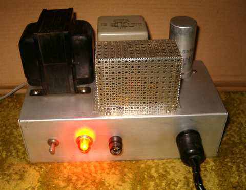
Home brew power supply
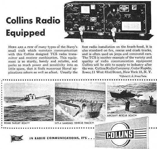
Collins placed this wartime informational ad in several radio magazines.
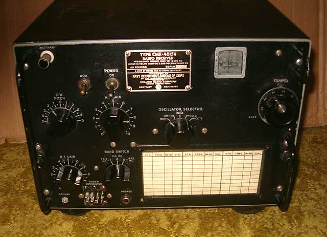
Navy TCS-12 receiver by Collins Radio Company
The Navy type CMX-46159 is better known as the TCS-12 receiver. The TCS was designed by Collins and used, along with its matching transmitter and a power supply, during World War II on LST landing craft, P-T boats, and a variety of other smaller boats as well as on-shore applications. This unit was assembled for Collins by Magnavox.
Frequency coverage is 1.5 to 12 MHz in three ranges. The receiver may be tuned and operated with either a variable master oscillator or at fixed frequency using one of four switch-selected pluggable crystal units. Each of those crystal units contains two crystals. One crystal is at 455KHz higher than the selected frequency for the superhet oscillator and the other is at the selected frequncy for use in spotting. The receiver has 7 tubes including a 12SK7 for RF amp, two 12SK7 for IF amps, 12SA7 for converter, 12SQ7 for detector and BFO, a 12A6 for master and crystal oscillator and another 12A6 for audio output. The antenna for which the TCS is designed is a 20 foot whip. Connections to the transmitter, power supply and accessories are by an 11 pin connector. That conector was replaced in this unit by a Jones plug.
Collins placed this wartime informational ad in several radio magazines.
Home brew power supply
As noted on its nomenclature plate, the TCS-12 receiver requires 220 volts of B+ at 100 milliamps and 12 volts at 1 amp for the filaments. The standard power supply unit for the TCS included two dynamotors operating from 12 volts. Other power supplies for higher voltage input were also available.
This TCS-12 was purchased at a hamfest (amateur radio swap meet). It came with a homebrew power supply pictured above which is rather well designed. It includes a relay (under the cane-metal shield) that must be energized by the receiver in order for B+ to be available. The power supply has its own ON-OFF power switch with pilot light. When the power supply is energized, filament voltage is available. The receiver's own ON-OFF switch is used for Standby and ON. When switched to ON, it grounds and completes the relay coil circuit in the same manner as a typical push-to-talk circuit. That relay then switches B+ to the receiver. The relay causes the power umbilical to have no B+ until the cable is properly connected to the receiver and the receiver's power switch is turned on. When the relay is not energized, B+ is fed to a bleeder resistor in the power supply. The safety aspect of using the relay is, if the ground connection which is also the B- return was somehow broken, the relay would not be energized.
The 6.3 volt and 5 volt secondaries of the supply's power transformer are wired in series for the filaments. The slightly reduced filament voltage (11.3 volts) does not seem to affect the operation of the set.
Repairs
The set worked when powered up but was not as sensitive as I would have expected given its two stages of IF and one stage of RF amplication. I checked all of the tubes in a TV-7 tube tester. One 12SK7 was found to be weak and was replaced. I also fed the receiver filaments with the full 12.6 volts to verify that the slightly reduced voltage was not a factor in the reduced sensitivity. I also suspected that the alignment was off. I tweaked all of the alignment adjustments. The converter alignment was found to be off significantly. Tweaking it for each band made a major improvement in sensitivity. I also checked the AVC line and the screen voltages and replaced a couple of off-value resistors. The bathtub bypass capacitors were surprisingly in very good shape after all these years.
The set had come with an external speaker with matching transfomer. In checking the impedance match of that transformer, I found a significant mismatch. I replaced the transformer with a proper 600 ohm to voice coil unit.
After all these changes, the radio performed as expected. Sensitivity with a short antenna was very good and reflects the design of the set.
This set has no discernible backlash. Cleaning and lubricating the tuning gearing improved the feel and smoothness of tuning.
This set was missing the paper frequency and dial setting card (on the lower right of the front panel). My thanks to K4CHE who provided a scan of his card from which I was able to print a reproduction.
Operating the set
On the lower ham bands, the lack of electrical bandspread as well as the relatively wide selectivity makes tuning somewhat difficult. However, this receiver is a very nice performer for short wave listening.
Used through the 1960's
I had assumed that the TCS lasted only through WWII and shortly thereafter, but I received the following notes on later experiences with the TCS from Tom WA0EAJ, Don W9CW, and Al W6DZ
Tom WA0EAJ wrote:
My Buddy Don, another old RM Chief, used a TCS on the USS Surfbird, and also remembers the clacking of the evil keying-relay.
TCS's were used on patrol boats, early river-patrol boats in "French Indo-China", and in aircraft.
Our TCS "combo" was vertically oriented and was a "grey front" version. It's entire purpose was as backup, and when I returned for the disestablishment (decommissioning for shore stations) in 1998, the radios were all gone, but the old antenna mount was still attached outside. The units were most often used with the "Standard US Navy 35' whip". The 20' antennas were for PT's and other patrol boats, but on shore stations and aboard ship (used as Radio-II backup), they ALWAYS fed to a 35 footer.
I would often tune it up on 75m phone, and check into some of the California AM nets of the day, on Sunday mornings when nobody was around.. figured it was the best "operational check out" that could be done. I once tried it on our 4335 kc CW net, but the clattering of the relay-keying was waaaaay too noisy, so decided on phone. Later on, they took our CW net away, and stuck us on 2268 kcs (horrible propagation), so the TCS would often be used for in-close communications (the 35' vertical would often out-perform our wire antennas on this freq).
They're built like tanks, and work pretty well, considering the vintage and what's inside. Nice to see another of the old girls, still making noise.
Sometime, very early in the morning... tune it onto 4335 kcs, and aside from the SITOR and AMTOR garbage, you'll hear an RTTY signal getting through the passband (it's up on 4337)... that's what I used to hear... all those years ago... even when I was in Vietnam. It was sort of an "old friend", having listened to it for several years.
As you've no doubt found, the units were either mounted side-by-side or with the receiver on bottom, then transmitter, then coupler on top. The original power supply is BIG and REALLY, REALLY HEAVY.
3 TCS's with power supplies would heat a moderately sized home.... hi hi hi It's the only COLLINS I ever owned, all by myself...
73 es ZUT,*
Tom WA0EAJ
(*ZUT is an UNofficial "Z" signal from the USCG RM's... means "CW forever")"
It wasn't the only WWII-vintage piece of gear we had aboard - we also had a RBO receiver!"
And the note from Al, W6DZ:
I was a navy ET stationed at Naval Air Station Glenview (IL) in the 50s and early 60s. Visiting the fire house to tune up the TCS rigs in the crash trucks was a morning ritual. Our maintenance vehicle (a WWII Jeep) had a TCS RX/TX mounted behind the passenger seat that looked exactly like the picture in the Collins ad. It found use when we had to contact the control tower to get permission to cross the runways. The navy’s crash boat in Lake Michigan near downtown Chicago was equipped with a TCS. Raising Glenview tower 20 miles away or Coast Guard Radio Northbrook (~25 miles) on 2182 for a radio check was always a treat during a crash boat visit. I don’t recall opening a TCS receiver or transmitter for service in the time I spent with them; the problems we had with those installations were all antenna related.
The TCS was eventually replaced by GE Progress Line FM rigs around 1958~1960."
73 & ZUT,
Al, W6DZ
An Adcom Linear Systems LSA-3 transceiver power supply was the previous item on the bench.