
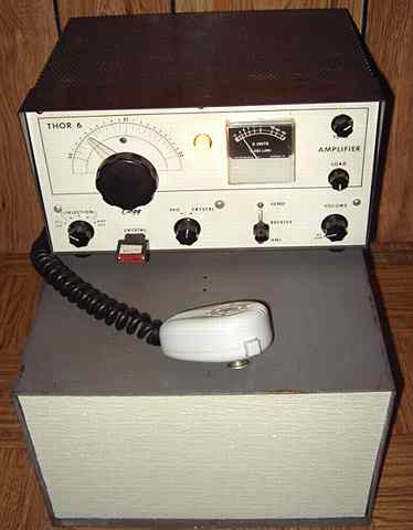
The Clegg Thor 6 transceiver was purchased at a hamfest. Designed for 6 meters, I noticed that it could be crystal-controlled but also had a VFO built in. That VFO tunes both the receive and transmit sections making it a truly modern transceiver. I asked the seller if he had a power cord. His answer was no. He apparently had never used the piece since it needed a lot more than just a power cord. Since it was light in weight, I correctly assumed it needed an external power supply.
That missing second chassis
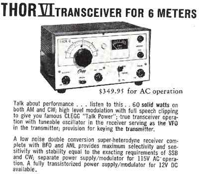
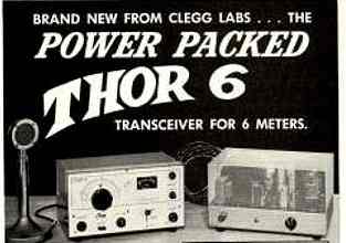
This was the first time I had seen a Clegg Thor 6. What I did not realize when buying it was that it needed not only an external power supply, but that the factory power supply included the built-in plate modulator. One cannot simply substitute a generic power supply. As shown in the ads, the Thor 6 and its original power supply/ modulator sold for $349.95, serious money in 1963.
Testing the receiver portion
I located a 12 pin Jones female connector and wired up the 12 volt filament and the receive B+ connections. Using the bench Heathkit variable power supply, the receiver came to life. I adjusted the VFO trimmer cap so that the tuning dial was accurate. With its Nuvistor tube front-end, the receiver performed quite well. It was very sensitive although it could be overloaded by a strong nearby sigmal. Checking the RF output of the driver tube showed that it was producing RF at the same correct frequency as receive . Since I wanted a VFO-controlled 6 meter rig, I decided to homebrew a companion power supply/ modulator using primarily junk-box parts.
Power output specs
The RF output tube for the Clegg Thor is a 6883, a 12 volt version of the 6146. With 560 volts on the plate, the RF input power is rated at a maximum of 62 watts with an RF output of about 40 watts.
Homebrewing a "junk box" power supply / modulator
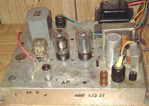
I had a junk box Magnavox AMP-175FF stereo tube amplifier chassis. Its tubes, output transformers, external preamp, and console cabinet were already missing. Its power transformer had a pair of 6 volt windings that could be wired in series for the required 12 volts of filament. Its 6 pin and 9 pin on-board jacks could be re-used for connecting to a wire harness to the transceiver's 12 pin Jones jack. The power transformer could handle the wattage and be close to the right voltage if converted to the "economy power supply" as described in ARRL Handbooks.
Economy power supply
An "economy power supply" uses a solid-state bridge rectifier and a center-tapped power transformer to supply both the normal receiver voltage, 255 for this unit, and the typical transmitter voltage requirement of double that, over 500. The receiver voltage is taken from the transformer's high voltage center tap and the transmitter voltage from the full bridge.
Choke input
As expected, a capacitor input filter resulted in too high a voltage. I opted for choke-input filtering using a couple of junk-box chokes. After the choke for the transmitter voltage, I used a pair of electrolytics in series along with balancing resistors and a bleeder. For the lower receive voltage, I also added a choke but used the amp's original electrolytic filters.
Choice of output tubes
The factory Clegg modulator uses triode-connected 6BQ6GTA sweep tubes in class B. The audio amp junk chassis originally used 2 sets of push-pull 6V6 output tubes for stereo. I opted to use just one pair of 6L6GC audio tubes. The cathode bias resistor was changed to accommodate the 6L6GC pair. Coupling caps to the 6L6GC grids were reduced in value to 0.01 uF to cut back on the bass response and possible hum as suggested in several ARRL Handbooks.
Circuit changes
The junk chassis used a 12AX7 tube for preamp and phase inverter. I kept that circuitry. A UTC S-19 modulation transformer with a 30 watt rating was added for output to the transmitter. The Thor transceiver has an onboard microphone preamp tube with a cathode-follower output to the modulator. The factory modulator uses a matching transformer to match the cathode-follower to the phase inverter. Not having a matching transformer, I opted to use a load resistor instead.
Relay power and screen supply
The modulator/ power supply also needs to provide 12 volts DC for a relay on the transceiver as well as the modulator chassis. The factory Thor modulator rectifies the 12 VAC filament line for the relays. I copied that circuit as well as the screen supply divider. The Thor modulator schematic uses four carbon resistors in series-parallel and a pair of ceramic caps to feed the RF power amp screen grid as a tap on the modulator plate output. As a result, the Thor uses both plate modulation and some screen modulation. I assume that Clegg used the four resistors to assure both power and voltage handling capability. Those resistors should be carbon rather than wire wound.
Adding a push-to-talk relay
To control the modulator/ power supply for push-to-talk, the Clegg needs a relay. An octal-mount DPDT transceive relay for B+ was added to the modulator/ power supply chassis. I opted to use the lower voltage source for the modulator tubes. The DPDT relay switches both sides of the modulator transformer, the lower B+ used for the modulator tubes on the primary side and the higher B+ to the transmitter on the secondary side.
Junk box cabinet
A recycled oscilloscope cabinet fit the chassis well and is being used to house the modulator/ power supply. The cabinet and front panel need to be painted. Although shown with the Thor in the picture above, it would normally be located out of sight.
Testing the transmitter
Noise in the microphone brightened the dummy load. The modulator was working. Plate voltage was about 520 under load. I tested it on the air with the local 6 meter net, receiving good reports on both audio and signal strength. An oscilloscope check showed that modulation was limited to about 80%. I suspect that the load resistor substituting for the cathode follower transformer might have been limiting the audio drive.
Follow up
I temporarily lifted the DC to the modulation transformer secondary and connected an audio output transformer of 5000 ohms to speaker voice coil as its load. The purpose was to use a speaker to listen to the quality of the audio as well as the level. I tried substituting a grid to plate transformer for the cathode follower transformer. It improved the maximum level significantly but also introduced some hum. I ended up increasing the value of the cathode load resistor which increased the audio and modulation levels without the hum problem.
I widened the gap between the contacts of the transceive relay because I noticed a split second of sustained arc when releasing the mike key which caused the receiver's AGC to block for a second or two on occasion. I am using the relay in DPST mode so I increased the gap by bending back the normally closed contact pair slightly. (Normally closed describes the contact position when the relay coil is not energized. ) I also added Clegg's circuit of a resistor and cap in series across the relay's normally open contacts. Those changes solved the problem.
A Russian Antenna current meter was the previous item on the bench.