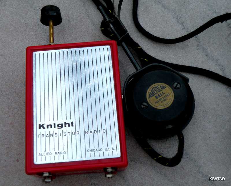
Knight-kit Trans-Midge one-transistor radio
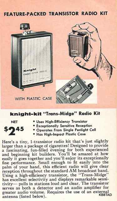
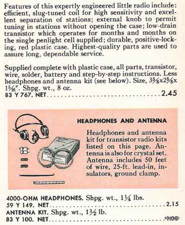
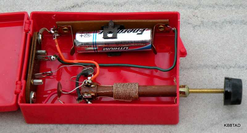
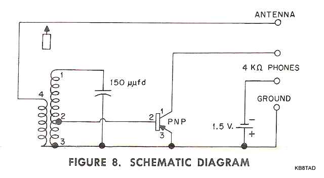
The Knight-kit Trans-Midge one-transistor radio certainly doesn't qualify as a boatanchor, but it was one of those Knight Kits that I would wonder about in the 1959 Allied catalog "Wish book". The six page fold-out "manual" is dated 1957. The red plastic case is about the size of a typical shirt-pocket transistor radio of later years but this one is the minimum possible to still qualify as a transistor radio. It uses a variable permeable coil and fixed cap for tuning, a single "AA" battery, one unmarked germanium PNP transistor, and pin jacks for connecting high impedance headphones. The single transistor acts as both RF detector and as amplifier. The headphones were sold separately. The little set looked to be in very good cosmetic condition. I purchased it at a swap meet with the matching Allied Radio "American Bell" 4000 ohm headphones.

An interesting job of soldering
I checked the lone transistor with an ohmmeter to verify its condition. Imagine my surprise when I got no continuity whatever between any of the legs in either forward or reverse polarity. I couldn't even get any continuity between the wire legs of the transistor and the coil connections. I then checked for continuity from the wire leads to the hook up wires. Nothing. Was it bad solder joints? The connections looked nice and shiny. I touched one of the solder joints (lower right solder lug in picture below)with my soldering iron and watched the "solder" on the joint smoke a bit and shrink! Not believing what I had seen, I squeezed the edge of one of the "solder joints" and found it to be flexible. Then it dawned on me. Someone had "soldered" all the joints with "liquid solder".
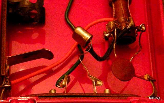
De-constructing a kit
To protect the plastic case while removing the liquid solder, I decided to remove all of the components in order to more easily clean off the "liquid solder" joints. I found that I could crush the joints with long-nosed pliers and the substance would crumble to dust. I easily cleaned all the joints of the pieces and parts, even the three pre-cut pieces of color-coded hook-up wire as supplied in the kit.

Testing the result
I hooked up the little set to my 80 meter dipole antenna. With the tuning coil all the way down I could not find any stations. I connected an audio amp in parallel with the headphone tips. With the amp, I could hear radio stations. The tuning coil all the way in was at too low a frequency. As I unscrewed the tuning coil some more, I started hearing and tuning different AM broadcast stations. The little set was working. When I finally tuned a local station at its night-time power, I could disconnect the audio amp. The sound from the headphones was loud enough to easily hear the program. I found the tuning even with only one tuned circuit to be fairly sharp compared to similar minimalist radios I had used.
Listening again in daytime
I listened again the next day to the "fifties" music of the same local AM broadcast station on daytime power. The level of volume was such at peak tuning that the Allied "American Bell" headphones were actually distorting a bit. I also tried my vintage Baldwin headphones which are known for quality and sensitivity. The Baldies were somewhat louder and I could tune in a weaker station and listen comfortably. With such volume from a good antenna and just one transistor, I decided to try connecting a loudspeaker with output transformer. The sound level was low but it actually worked.
I found the tuning range to be from just below the broadcast band to an upper limit of about 1320 KHz. Since the 150 pF ceramic cap was the original, I decided to leave it as constructed and not try a lesser value cap. The loud 50's music daytime station was just below 1000 KHz so that was not a problem for me.
Long antenna needed
The kit instructions and the catalog are very clear about needing a proper outdoor antenna. One is definitely needed.
Did you build one of these little sets in the late 1950s? Let me know what results you had.
A Hallicrafters TW-1000 was the previous item on the bench.