Old Viking boat(anchor) ready to travel the waves again. 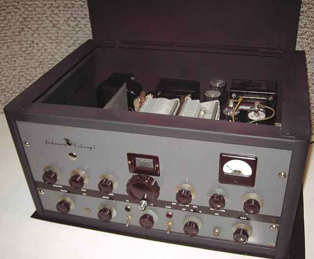
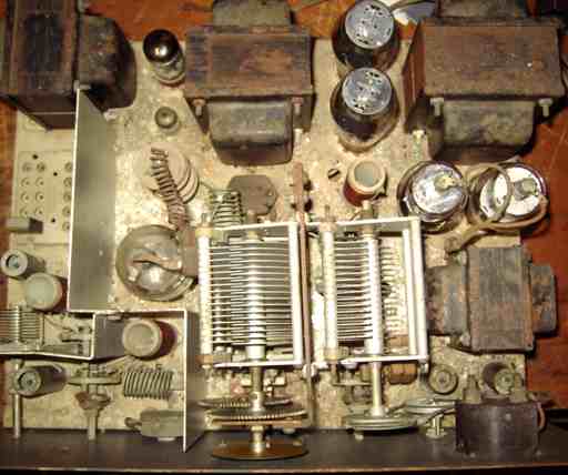
The Johnson Viking I transmitter kit cost $209.50 in 1949. That price did NOT include the tubes. Input is 150 watts according to the ad in the 1950 Radio Amateur's Handbook. According to the 1951 ads, it is "conservatively rated at 100 watts AM phone output and 115 watts CW". It covers the ham bands from 160 to 10 meters. The final RF amp tube is a Raytheon 4D32. It is a very tough tube that is not heavily loaded in the Viking. Few transmitters use the tube which was once considered expensive. A few years ago, a large number of these tubes were released from Air Force surplus and the price is now more reasonable. The transmitter also uses push-pull 807 tubes for modulators running class AB2. Three 6AU6 tubes are used as RF oscillator, audio preamp and audio driver. A 6AQ5 is used as buffer. Rectifiers are 6AL5 for bias, a 5Z4 for LV B+, and a pair of 5R4 for HV B+. Continuous final tank tuning is provided by a rotary inductor geared in tandem with a variable capacitor for all bands 80 through 10 with a switched inductor added for 160 meters.
Old Viking boat(anchor) ready to travel the waves again.
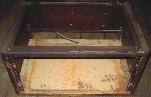
This Viking I was purchased at a hamfest. Both the seller and I were thinking parts set because of the apparent corrosion on the chassis and rust on the transformers and the rack-mount cabinet. What I did not realize when buying the Viking was that the chassis was made of aluminum and could be cleaned up rather well. The Viking has a non-original hole in the front panel. I opted to use a hole plug to cover it, hence the bright chrome button under the Viking logo.
Since the Viking started life as a kit, all of the fasteners were screws rather than rivets. That made it relatively easy to remove parts such as the partition shields in order to clean and service the transmitter.
Repairs
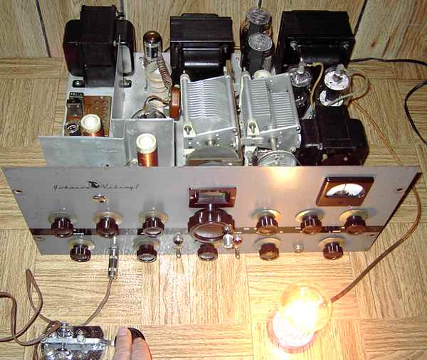
I removed the shield partitions to enable cleaning. After some difficulty removing the knobs, I succeeded in removing the front panel.
Both pilot light assemblies needed to be replaced because of the danger of short circuits. The fiber insulators and the rivets would not hold the parts in place and a short to chassis was possible.
All switches, the drive control, and volume control were cleaned and checked for function and good continuity. All of the transformers were also tested for continuity and leakage. Both power switches were open but a thorough application of contact cleaner through the front bat handle openings brought the switches back to proper function. All tubes (except the 4D32) were tested. A proper fuse was installed. Each of the three power supplies was tested in turn starting with the bias, then the 300 volt LV B+ supply, and lastly the transmitter plate supply. The bias supply voltage, fed by a 6AL5 rectifier tube, was found to be low. Proper bias voltage is especially critical in class AB2 modulators. Replacing the electrolytics solve the problem. The original caps were left in place for cosmetics but connected only to ground. A bad contact on one of the 5R4 sockets was repaired.
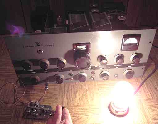
Viking rides the waves again!
After thorough cleaning and repairs, the tune-up procedure as listed in the very complete manual (from BAMA) was followed exactly. The four-position metering system helped to make the testing easier. With a 40 meter crystal plugged in, the meter and a frequency counter were used to test the oscillator first and then the buffer. Finally, the plate power switch was turned on and after adjusting the drive and the final tank, the 120 watt dummy load lamp began to glow. Subsequent adjustments caused it to glow to full output as can be seen from the photos. The AM function also worked well. Repainting the rack cabinet completed the repairs.
Viking impressions
The Viking is a very conservatively made transmitter with high quality Johnson porcelain components and that neat continuous-tune final tank. Johnson later came out with an upgrade kit to shield the meter and other RF openings, but TV interference is much less of an issue now than in the early 1950s. It is a very desirable transmitter that should see considerable further usage.
Its ham-radio history
This Viking I came with a W8RSY dymo label on the front. W8RSY was not the seller. On attempting to e-mail him regarding details for the Viking, I learned that he was a recent SK. His XYL graciously answered my inquiry and noted that she had found a copy manual for the Viking. I am sure that W8RSY would be pleased to know that his Viking will again ride the ether waves.
The Progressive Radio Edu-Kit was the previous item on the bench.