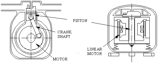
Background - The very impressive Athens based R&D company, Sunpower, Inc, was formed by William Beale in 1974, mainly based on his invention of the free-piston Stirling engine. The free-piston configuration enabled Sunpower over the years to develop an internationally recognised expertise in linear motors and generators, and one of the byproducts of this development is the oil-free linear compressor for refrigeration applications.
The following drawing is reproduced from a paper by Sunpower (unfortunately no longer available on Sunpower's website), and illustrates the significant difference between a regular mechanical slider-crank compressor mechanism and the linear compressor:
Some of the major advantages of the linear compressor are:
It is oil-free - librication is provided by gas bearings on the cylinder wall and a piston support mechanism which allows contact free oscillation of the piston. This enables usage with refrigerants which would degrade over time while in contact with oil as well as provide extremely quiet long life operation.
Both the amplitude of oscillation and the mean position of the piston can be controlled allowing the refrigeration system to maintain a high Coefficient of Performance (COP) under part load conditions. Since the refrigerator is one of the major energy users in the US (continuous operation) any savings in energy for the same performance is significant.
Sunpower exhibited the first commercial refrigerator using the linear compressor at the Sustainability Fair, which took place in the Athens Fairgrounds on October 14, 2001 (see picture). This is an extremely quiet and very impressive machine, and is manufactured by LG Electronics in Korea.
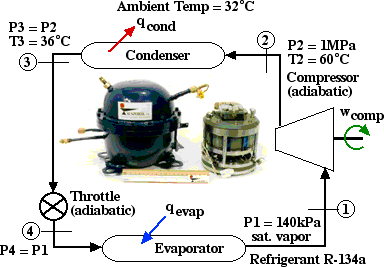
![]() Problem
4.7 - We wish to do a
preliminary thermodynamic evaluation of a refrigeration system
designed for home usage which will use the linear compressor with
refrigerant R134a. Consider the following system flow diagram (Note:
the picture of the Sunpower linear compressor was taken from
Sunpower's website with permission, however all other values shown in
this diagram are pure speculation on the part of your instructor for
purposes of this exercise):
Problem
4.7 - We wish to do a
preliminary thermodynamic evaluation of a refrigeration system
designed for home usage which will use the linear compressor with
refrigerant R134a. Consider the following system flow diagram (Note:
the picture of the Sunpower linear compressor was taken from
Sunpower's website with permission, however all other values shown in
this diagram are pure speculation on the part of your instructor for
purposes of this exercise):
Note that prior to doing any analysis we always first sketch the complete cycle on a P-h diagram based on the data provided. Using the data provided on the above schematic we first plot the four processes on the P-h diagram as follows:
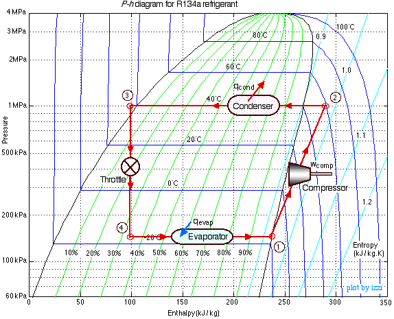
Notice that no mass flow rate has been provided, thus all energy solutions should be specific quantities [kJ/kg]. Using the R134a refrigerant tables to evaluate the enthalpy at all four stations determine the following:
a) Determine the work done on the compressor [-54 kJ/kg].
b) Determine the heat absorbed by the evaporator [137 kJ/kg], and that rejected by the condenser [-191 kJ/kg].
c) Determine the Coefficient of Performance of the refrigerator (COPR) (defined as the heat absorbed in the evaporator divided by the work done on the compressor - always presented as a positive value even though the work done wc is negative) [COPR = 2.53].
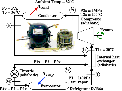
![]() Internal
Heat Exchanger Addition - On
a previous tour of Sunpower (October 2005) we were told by the
engineer in charge of linear compressor development (Robi Unger) that
it is common practice in the refrigeration industry to use an
internal heat exchanger to subcool the refrigeramt at the outlet of
the condensor by means of that exiting the evaporator and thus obtain
a much larger refrigeration capacity using the same components. Using
that information we have constructed a new system flow diagram as
follows:
Internal
Heat Exchanger Addition - On
a previous tour of Sunpower (October 2005) we were told by the
engineer in charge of linear compressor development (Robi Unger) that
it is common practice in the refrigeration industry to use an
internal heat exchanger to subcool the refrigeramt at the outlet of
the condensor by means of that exiting the evaporator and thus obtain
a much larger refrigeration capacity using the same components. Using
that information we have constructed a new system flow diagram as
follows:
Notice that we have included an internal heat exchanger that heats the refrigerant exiting the evaporator (as a saturated vapor at 140kPa) to 20°C. We have chosen a state numbering system (1x, 2x, and so on) so as to allow the new system to be plotted on the same P-h diagram as above, and thus to be able to qualitatively compare the increase and improvement of performance provided by adding the internal heat exchanger. We first augment the above P-h diagram as follows:
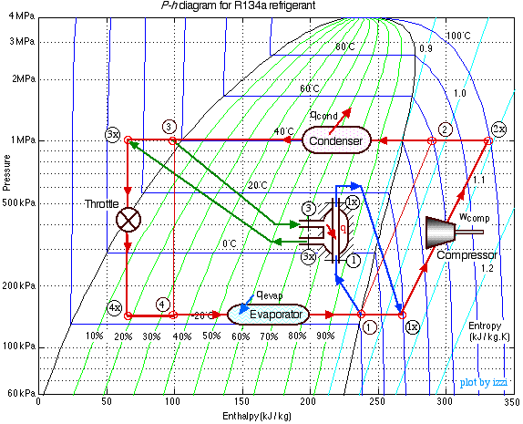
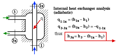
In order to determine the new value of enthalpy at state 3x we consider the heat transferred in the heat exchanger as in the following diagram:
Notice again that no mass flow rate has been provided, thus all energy solutions should be specific quantities [kJ/kg]. Using the R134a refrigerant property tables to evaluate the enthalpy at stations (1x), (2x), (3x), and (4x) determine the following:
d) Determine the work done on the compressor [-63.7 kJ/kg].
e) Determine the heat transferred in the internal heat exchanger, assuming it to be externally adiabatic [32.2 kJ/kg], and the temperature of the subcooled liquid entering the throttle (3x) [13.4°C].
f) Determine the heat absorbed by the evaporator [169 kJ/kg],
g) Determine the heat rejected by the condenser [-235 kJ/kg].
h) Determine the Coefficient of Performance of the refrigerator (COPR) (defined as the heat absorbed in the evaporator divided by the work done on the compressor) [COPR = 2.65].
Finally, comparing the two systems compare their
respective performance and discuss the
results.
____________________________________________________________________________________________