Problem 6.12 - Actual Power Output of the T700 Gas Turbine Engine
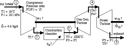
In Solved Problem 6.11 we did an ideal thermodynamic analysis of the General Electric T700 helicopter gas turbine engine, shown in the following schematic diagram:
Notice again that there are two turbines operating on independent output shafts. The High Pressure (first) turbine, named the Gas Generator turbine, is directly connected by a shaft to the compressor. Its sole purpose is to drive the the compressor, thus the energy output of this turbine must equal the energy consumed by the compressor. The Low Pressure (second) turbine, named the Power turbine, is connected via gearing to the helicopter rotor.
Notice that in Solved Problem 6.11 we assumed that the compressor and both turbines were isentropic. In this exercise we wish to extend the analysis to non-isentropic compressor and turbines. Assume that the compressor adiabatic efficiency ηC = 88%, and that each turbine has an adiabatic efficiency ηT = 86%. Using the information shown on the schematic diagram above, do the following:
a) Sketch the entire process on an h-s diagram, clearly showing the 5 stations on the diagram and the relevant isentropic and constant pressure lines. Indicate the relevant actual and isentropic work values on the sketch.
b) determine the actual energy consumed by the compressor [wC,act = 373 kJ/kg], and the actual temperature at the outlet of the compressor [T2a 628K].
c) determine the heat energy absorbed by the working gas in the combustion chamber [qH = 709 kJ/kg].
d) determine the actual temperature [T4a = 934K] and the pressure [P4 366 kPa] at the outlet of the gas generator turbine.
e) determine the actual temperature [T5a] and energy output of the power turbine [wPT,act 252 kJ/kg].
f) given that the mass flow rate of the working gas through the system is 4.6 kg/s, determine the actual power output of the power turbine [1161 kW].
g) determine the thermal efficiency (ηth) of the T700 gas turbine, compare this value to the equivalent reversible thermal efficiency and discuss your results.
Derive all equations used starting from the basic energy equation for a flow system, the equation of enthalpy for an ideal gas (Δh), the basic definition of compressor and turbine adiabatic efficiencies (ηC,ηT), the basic definition of heat engine thermal efficiency (ηth), and the temperature/pressure relation for the isentropic process of an ideal gas:
Use specific heat values for air at 800K (CP= 1.099 [kJ/kg.K], k = 1.354)
(Hint: refer to the Adiabatic Efficiency Summary Sheet to determine the effect of compressor and turbine efficiency. Don't forget that the gas generator turbine must always supply the power required by the gas compressor)