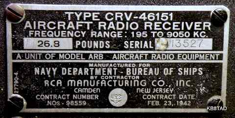
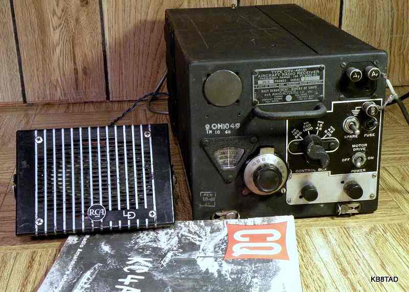
Navy ARB Aircraft Radio Receiver
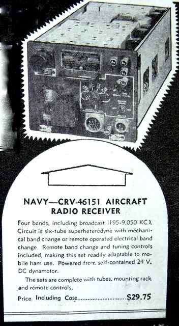
The ARB is a World War II US Navy aircraft radio receiver system. The Navy identifies the receiver as part number CRV-46151. Frequency coverage is continuous from 195 KHz to 9.05 MHz in 4 bands. The manufacturer was RCA. The ARB uses two different IF frequencies, 135 KHz for the VLF and Broadcast bands and 915 KHz for the two shortwave bands. The IFs are automatically selected by the bandswitch. The 915 KHz IF can also be switched by a relay for either narrow or broad bandwidth.
Ham radio modifications
Like much military hardware from WWII, the ARB was sold on the surplus market. This 1947 ad is from Radio News.
Repair notes:
This ARB unit did not work at all when purchased. A female Jones connector for AC power had been installed on the rear panel of the ARB requiring a dangerous power cord with two male connectors. That was removed and replaced by a directly connected 3-wire shielded power cord with the safety ground attached to the chassis. An inline fuse was added. A phone jack had also been installed on the rear panel. A speaker was connected by way of that phone jack but there was no crackling noise when the prods of my VOM on low range were touched to the output transformer primary of the ARB. I always use that un-powered test to verify that the audio output transformer is intact and has a proper load. The problem turned out to be the phone jack itself which needed an application of deoxit.
The radio was powered up slowly while monitoring the B+ and the current draw. However, there was no sound. My signal tracer found a proper signal at the volume control. The 12SQ7 had been bypassed. The problem turned out to be a bad audio output tube. Replacing the 12A6 brought some life to the radio, but the disconnected 12SQ7 meant limited volume. I suspect the 12SQ7 had been by-passed in a prior effort to solve the audio problem. The poor connection on the phone jack may have contributed to the dead audio output tube.
Repair follow-up:
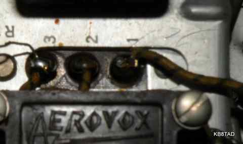
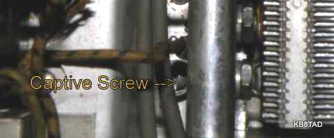
The radio was functional on all four bands but needed a bit of wiggling of the bandswitch to work properly. That could probably be cured by applying deoxit to the bandswitch. The problem was getting to that bandswitch. The bandswitch is totally enclosed by the separately-shielded coil boxes for each stage. I queried a boatanchor net forum for info on getting to the bandswitch assuming that I might have to remove the separate shield boxes. Robert WA5CAB answered my query with a page from the manual which provided the instructions for doing exactly that. Each separately shielded stage box has two screws on one side that are obvious and one not-so-obvious captive screw next to the variable capacitor. The terminal connections for each shielded stage also have to be unsoldered on the bottom as shown in the picture and also under the tube shelf.
Repairs were followed up by reconnecting the 12SQ7 audio preamp stage. That made a major difference in audio with almost too much gain.
Powering the IF bandwidth relay
The relay for changing the IF bandwidth was not working. I traced the front panel switch wiring to the relay. It was intact. I decided to remove the CQ-article recommended B+ wiring to the relay since that modification placed 220 volts of B+ on a relay coil designed for 28 volts. I tested the relay coil with an external low voltage power supply. It needed a minimum of about 15 volts at about 80 mA to actuate. The B+ draw for the set was about 70 mA, too little for the relay. I decided to use the 12 volts of filament by installing a 1N4007 diode in a half wave circuit with an electrolytic with another diode across the relay in reverse bias to limit voltage spikes from the coil. I first used an electrolytic that was too small. A second attempt with a 1000 MF electrolytic easily did the trick.
Using the ARB
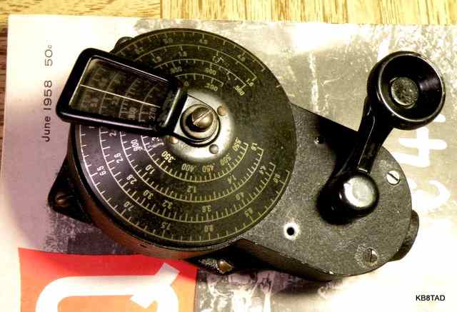
The ARB is one of very few military receivers with the broadcast band. It is a delight for broadcast band listening and DXing. The low IF makes for very good selectivity although it limits the audio bandwidth a bit. Sensitivity for the 80 and 40 meter ham bands as well as general shortwave listening is also very good. The ham who originally converted this set added a good vernier control for tuning without backlash. I had some difficulty with the level of BF oscillator injection for SSB but re-connecting the 12SQ7 audio stage helped since I could crank the audio to a higher level and cut the RF gain back for improved BFO. Bandwidth for amateur radio, even at the narrow IF setting, is still too wide for most users. This set will find its best use for shortwave and broadcast band listening.
Accessory Direction Finder
The ARB power socket and relay-actuated separate antenna connections could also be used by an externally powered loop direction finder, the DU-1, which was useful for navigation with lower frequency beacons or broadcast band transmitters.
Information and pictures of the DU-1 direction finder, a restored ARB, and more information can be found in this excellent web article from Ray VK2ILV.
Introducing the ARB and the matching ATB transmitter to the Navy, 1942
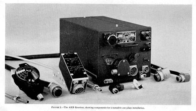
The ARB, its accessories, and description along with an excellent schematic is found in this October 1, 1942 Navy Radio and Sound Bulletin article placed on the web by aafradio.org. The article states that the ZB 246 Megacycle homing adapter known as the ZB adapter and later as the AN/ARR-1 could be connected to the loop antenna terminals and be powered by and snapped in place on the studs on top of the ARB case.
The ZB homing system
The ZB system was a rather ingenious method, classified until 1947, of homing in to an aircraft carrier. The carrier sent out a Morse code letter for every of 30 degrees of the carrier's compass direction points synchronized with the position of a rotating antenna. The coded letters for each of the twelve compass points were changed each day and sent as Modulated CW (Morse code tones). The code was modulated in the lower part of the broadcast band (for example at 800 KHz). That broadcast band RF signal was then used to further modulate the 234 to 258 Megahertz VHF signal (called UHF in the era). The VHF signal was mostly line-of-sight. If the pilot could hear one or two of the Morse code letters, he would know his relative position to the carrier. The double modulation would make it difficult for an enemy to easily detect the MCW content of the signal. The VHF signal was reportedly reliable to about 40 to 70 miles out for an aircraft at 10,000 feet and further at higher altitudes. The accessory ZB adapter was a relatively simple VHF receiver that would demodulate the received signal back to the lower portion of the broadcast band and the MCW signals were then detected by the ARB.
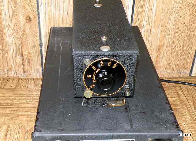
My ZB adapter
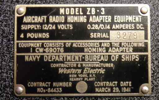
While reading information on the ZB system, I realized that I already had a ZB adapter, a model ZB-3 purchased at a hamfest several years earlier.
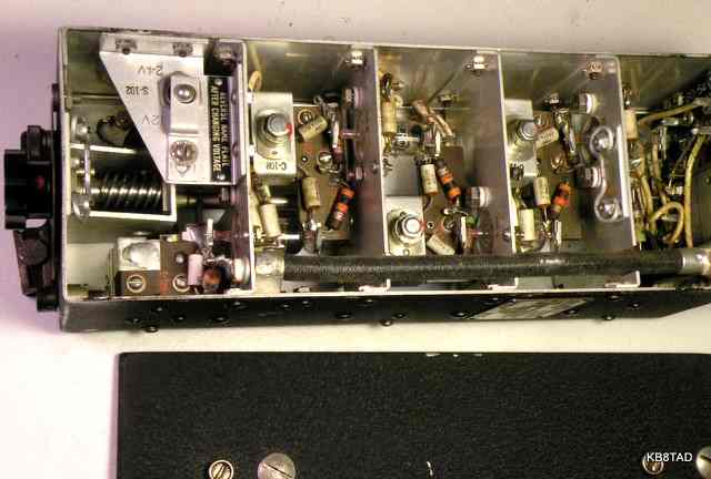
It has the standard set of four type 954 acorn tubes. The ZB adapter does indeed match the studs on top of the ARB. The forward stud on my ham-modified ARB is missing, but the shock mount on the ZB-3 would have fit the studs perfectly.
Antique Wireless Association article
Frederick Chesson's interesting story of the ARB which he purchased as a teenager for Christmas 1949 and then modified is written in the Antique Wireless Association's August, 1990 issue of the Old Timer's Bulletin
Real experiences using the YE-ZB aircraft carrier homing system
This excerpt from a Google book accurately portrays
the ZB homing system while describing a harrowing and tragic experience of a group of Navy pilots attempting to return to their carrier during World War II.
Send me your experiences with the ARB and the ZB system
If you used the ARB and the ZB homing system to locate and return to your aircraft carrier in World War II, send me a note on your experiences. (e-mail link is on my home page).
3-15-10
The Knight-kit Trans-Midge one-transistor radio was the previous item on the bench.