
The text in this illustration from the Rider Chanalyst brochure reads:
Locating point of disappearance of signal with the RF-IF channel.
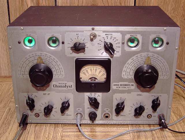
What? Not another Rider Chanalyst model 11!
Yes, Another great old Rider Chanalyst has found its way to my work bench. This is my third one. I guess I can't help the attraction. It's those four green eyes winking back at me and the TRF tuner just crying to be restored to making AM broadcast sound. This is another model 11 Type A, Serial #1865, from 1938-39 by Rider's Service Instruments Co. For more information on what these instruments can do, see my earliest page on the Chanalyst. Here's the page for the second Chanalyst . I also repaired a Meissner Analyst that is almost a pure copy of the Rider Chanalyst.
I also repaired a later RCA model 162C version of the Rider Chanalyst for another hobbyist but did not illustrate that repair. In 1940, the Chanalyst cost was $107.50.
Locating point of disappearance of signal with the RF-IF channel.
Designed by John F. Rider
Rider is a well-known author and radio repair book publisher of the era. Rider wrote a two-part article for the October and November 1938 issues of Radio Craft detailing the circuits and uses of the Chanalyst. The November issue has the original schematic. The Rider Chanalyst is named for its 5 independent sections called "channels". A brochure describes how a radio could be hooked to all 5 sections of the Chanalyst to monitor for intermittent faults.
The five "Channels"
The five sections include a one stage audio amplifier, a wattmeter, a 3 stage TRF tuner covering 95 KHz through 1700 KHz which is intended for tracing RF and IF signals, and a single stage TRF covering 600 KHz through 18 MHz for checking a receiver's local oscillator. Each of these "channels" uses a tuning eye indicator. The fifth "channel" is a center-zeroing 11 MegOhms-per-volt vacuum tube voltmeter. The Type "A" variation of model 11 added pin jacks so that voltage output readings could be taken by that voltmeter of the RF-IF channel and the Oscillator channel.
Repairs and testing
As usual, I checked for any line-to-chassis leakage and for a proper level of high resistance in the B+ line. The line to chassis caps were leaky. I decided to remove them. They were no longer needed in this circuit because I replaced the power cord with a modern 3-wire grounded version. The electrolytic had been replaced by a former owner with three smaller caps under the chassis. They were still in good order.
I found that the power switch was open. I had to move the shielded oscillator coil box aside since it was blocking access to the power switch. I dismounted the switch and sprayed contact cleaner directly through the openings on the switch body for a successful repair. I removed the lid to the copper bandswitch box and used contact cleaner on the bandswitch and all the other controls and switches.
Eye tubes all aglow
After a slow power up, the Chanalyst showed signs of life. The B+ was stable and the eye tubes showed green. One eye tube looked new. It had apparently been replaced by a former owner. The other three were obviously worn in the section of the eye that is always on (the upper 3/4 of the eye circle). The indicating portion for each eye (the lower quarter) was still in good shape for two of the tubes and a bit worn in the fourth eye tube. All were still usable. New eye tubes are relatively expensive. If the indicating portion of the eye (the lower 1/4) is good, I tend to leave them in place. I measured each of the 1 Megohm resistors on the eye tube sockets. All were good. I replaced a number of the caps. I did not replace any of the the cathode bypass caps or several other caps that rarely see any voltage or are bridged with relatively low value resistors. While I expect to see a bit of leakage, at least one cap threw me a bit. The input cap to the audio channel showed no leakage. However, it also turned out to be open. Apparently one of its leads was no longer making contact with the foil inside. The audio channel which is basically a one-stage triode amp was working but had low gain. I replaced several of the high-value resistors that had drifted up in value but the culprit was that cap. The fact that it allowed some audio to pass through made the problem a bit harder to find.
Alignment of RF-IF channel
As expected, the RF-IF channel needed some alignment tweaking. Each of the three stages for each of three bands has a pair of trimmer caps. Some of the trimmer caps carry B+. One cap for each trimmer pair for each band peaks tuning for the stage. The other trimmer adjusts the stage gain by varying the coupling between stages. Those can be adjusted to the point of feedback at maximum RF gain. Back off the coupling somewhat if feedback is noted.
A nice TRF AM tuner
When aligned and working properly, the RF-IF channel (actually a three stage TRF tuner) has excellent sensitivity. It can directly feed the single stage audio channel for headphones or can be connected to a speaker with matching transformer (at a relatively low audio level). It can also provide a quality audio signal to an external audio amp.
Wattmeter and Oscillator channels
Both of these circuits needed the coupling and bypass capacitors and a couple of high value resistors replaced. The three-band oscillator channel can be adjusted to accurately indicate the presence of an RF signal such as from the oscillator of a superhet radio. I used a signal generator and frequency counter to accurately tweak the alignment. The wattmeter read low. The eye tube should just close when the front panel control is adjusted to read wattage draw. Again, leaky bypass caps and off-value resistors can cause problems with wattage accuracy.

Probes
Most of the Chanalysts are missing the probes, but those are easy to replace. The oscillator probe uses a 1pF cap for isolation. The VTVM probe uses a 1 MegOhm resistor. The RF-IF channel uses either the straight through audio channnel cable or a 100 to 1 attenuator cable for signal levels exceeding 3 millivolts. A phone plug to phone plug patch cord was also provided for connecting the RF-IF output to the audio channel input.
Chanalyst info resources
BAMA has the manual for the later RCA Rider 162C.
BAMA also has an excellent PDF copy of the brochure used by Rider in cooperation with RCA. Note that the brochure and the manual are listed under RCA.
The brochure details the varying ways in which the Chanalyst can be used to trace circuits and monitor intermittents. The testimonials by radio repairmen are interesting to read.
Here is one example:
"An intermittent sputtering condition of this kind is very difficult to locate and many excellent servicemen would spend hours in finding the source of the disturbance. With the aid of the Chanalyst, the source of this noise was quickly located in the plate winding of the second IF transformer. With the RF-IF probe on the plate terminal of the socket, each time the sputter occurred it caused a very noticeable movement on the Chanalyst eye."
"A check of this transformer by usual methods indicated continuity, which would have left the average serviceman at sea as to the cause of the sputter. "
George B. Jones
Jones Radio Company, Pottsville, Pa.
Update
This Chanalyst has moved its four green eyes to another good home. Enjoy it Jim!
12-07; update 11-09
A Heathkit SB-610 monitor scope was the previous project on the bench.