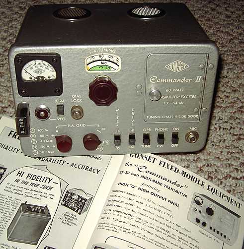
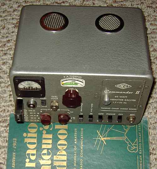
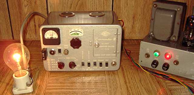
The original Commander was priced at $124.50 in this 1953 ARRL Handbook ad. A separate mobile power supply was available for $69.95. Compare the size of the Commander II to the size of the Handbook.
Repair progress
After a thorough cleaning inside and out with white waterless hand cleaner, this Commander II was in excellent cosmetic shape. I applied deoxit to all the slide switches, the oscillator bandswitch, the coil contacts, the Jones plug contacts, and the tube sockets. The slide switches are at the heart of the set and extra effort was needed to clear the oxidation. I tested each with an ohmmeter to verify good contacts. The buffer capacitor on the modulator was a Sprague "black beauty" capacitor known for frequent failure. Not surprisingly, it was leaky and was replaced with a modern cap.
All of the tubes tested as new on my military TV-7 except the 6146 which tested as weak. I connected a small power supply (see below) but was surprised by the set's low current draw and extremely weak RF output, barely managing a weak glow on a 7 watt night light. Could it be the 6146? Substituting a known good 6146 that had tested like new resulted in the same weak output. Something else was wrong. I checked the screen grid voltage. It was normal. And then it suddenly dawned on me. Why had I not noticed the 7C5 pair barely getting warm and the set taking so long before showing grid current? Sure enough, the Commander had been modified for 12 volts of filament and was getting only half of that. Tracing the filament line showed that the 7C5 pair and the 6AG7 wired in series with the 6146 and the 12AV7. Two quick wiring changes and the filaments were again connected for 6.3 volts. Now the little transmitter was finally showing some life with a proper size light bulb as dummy load. Subbing the supposedly weak 6146 showed no difference between the one checked as excellent and the one that showed as weak. Both were fine in the circuit. This had happened to me before. A 6146 that tests weak in my TV-7 tube tester may in fact be very capable of full output.
Power supply
Two high voltage feed wires are provided for the Commander. A 300 volt supply is needed for its low-level stages (oscillator and audio preamp). The same 300 volt supply can also be used to operate the high-level stages, the RF final and modulator plate supply. However, the manual also states that a 400 to 425 volt supply from a surplus dynamotor could be used for the high-level stages if a dropping resistor was added to feed the low-level stages and a larger screen resistor was substituted.
I had a small Lambda Model 25 regulated high voltage supply. Regulated output was limited to a maximum 100 mA, not enough for the Commander. Checking voltages on the Lambda showed that the capacitor input Pi filter produced nearly 580 volts that the two 6Y6 pass tubes dropped to a selected variable setting between 200 and 325. The two pass tubes were responsible for dropping around 25 watts of power. By simply changing the supply to choke input, the pass tubes ended up seeing only about 400 volts. Also, with choke input, a center-tapped-return power transformer can provide about 54% more current than capacitor input according to Hammond Transformer. There is no magic here and nothing gained or lost in total wattage. Essentially, the reduced (unregulated) voltage allows for an equivalent in more current. With reduced voltage input to the pass tubes, there is less stress on them provided there is enough voltage to do the job. I found that with choke input, the pass tubes still regulated fine if the regulated supply was loaded to less than about 60 to 70 mA, and I could use the now higher-current capability of the unregulated output directly for the transmitter's high-level supply voltage. I added a new output terminal to the Lambda to tap its unregulated voltage.
I connected the unregulated 400 volts to the Commander's hi-level feed wire and the regulated 300 volts to the low-level feed. Under load, the unregulated voltage dropped to about 360-370 volts. The Lambda transformer, rectifier and pass tubes all remain relatively cool despite the increase in total current output.
Coils
The Commander uses plug-in coils for its final. The coils are located behind the little door and are isolated from DC by the plate blocking capacitor. The topmost pin (pin 4) is grounded. Loading of the transmitter is by a tap on the coil. Link coupling can also be used. According to ads, the Commander came with two standard coils. This Commander only came with one of those coils, the G-40/75/80 intended for the 40 and 80 meter bands. It has 15 turns of 1 and 1/2 inch diameter air core and is 1 and 5/8 inches long. (about 6 uH) mounted on a 5 pin plug base. The coil has two small Fahnestock clips connected to pins 1 and 5. A wire to one of those Fahnestock clips goes to a small coil clip that can be moved to select the loading. Just that one wire and ground are used for unbalanced (coax-fed) antennas.
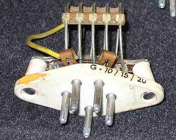
Rick Ferranti W6NIR supplied the following photo and description of the other standard coil for the Commander, the G-10/15/20. According to Rick:
Optional coils
Gonset offered optional Commander coils for 160 meters and 6 meters. If you have pictures and/or dimensions for those coils, please let me know.
Since these coils are all 5 pin plug-in units similar to the B&W "Junior" series and equivalent "75 watt" coils from Bud and other manufacturers, I checked to see if some of my junk box coils of that type would be plug compatible. Resonance was checked with a grid dip meter. I found a link-coupled coil that had been designed for 80 meter push-pull that should work quite well for the 160 meter band. The coil has a center tap connected to pin 3 which is not used by the Commander. It has two sections of 16 turns each (20 turns per inch of 1 & 3/4 inch diameter coil stock) with the ends connected to pins 2 and 4. It also has a 3 turn link between the two sections connected to pins 1 and 5 which are also used by the Commander for its link connections. No changes required. It resonated from 1.375 MHz at tuning capacitor max to 2.41 MHz at capacitor midpoint (PA tune at 50) and 4.84 MHz at capacitor minimum.
I tested another coil in the "boxe de junque" that will extend the Commander to 20 and 15 meter coverage and is similar to the original G-10-15-20 coil. The base of a 5 pin tube and some heavy wire can be used to homebrew coils.
More information on Commanders
There are apparently not that many Gonset Commanders in current existence. BAMA has a manual, but it is very poor quality. If you have a good manual, please scan it for BAMA.
Rick Ferranti, W6NIR (ex-WA6NCX) whose 10-15-20 coil is pictured above, has an excellent article on the Commander titled: Pocketful of Power: The Gonset Commander in AM Press Exchange #110. At the bottom of his article is a link to a Commander schematic .
Notes from a Commander user
Bill Macomber (ex-W1YAO) wrote:
The Clegg Zeus transmitter was the previous item on the bench.