Clegg Zeus 6 and 2 Meter Transmitter
How not to sell a radio
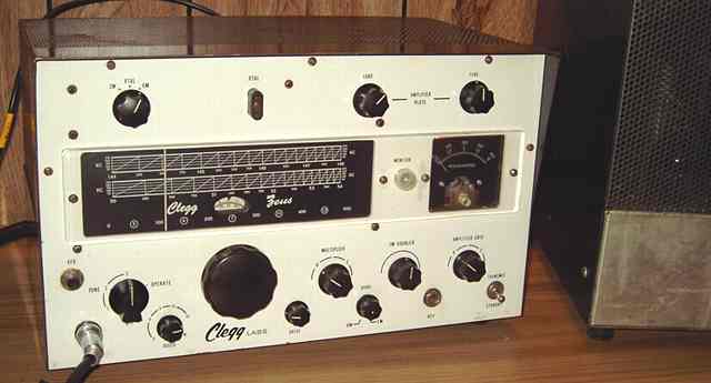
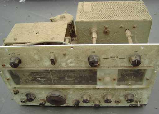
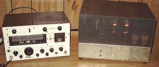
This Clegg Zeus 6 and 2 Meter Transmitter was purchased at a antique radio swap meet. It was crying to be either cleaned and refurbished or turned into parts. About the only guarantee for a set this dirty was that it probably had not been plugged in and tested. As you might expect, the price was inversely proportional to the amount of dirt on the radio. Fortunately, the Zeus was complete including the large Jones-plug interconnecting cable.
Another Clegg
The Zeus appealed to me because I had read about it when working on the nice Clegg Thor that I had previously repaired. The Zeus was Clegg's most powerful and expensive 6 and 2 meter transmitter. It can be crystal-controlled or used via a built-in VFO. Cost as listed in the ad in the 1963 ARRL Handbook was $695. (up from $675 in 1962). The matching Interceptor receiver, which I have yet to come across, was priced at $473. The combination was about half the price of an automobile, serious money in 1962-63. The 1963 Handbook ad described the Zeus as
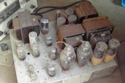
Not pictured in the Handbook ads is the rather large power supply/ modulator chassis. It weighs in at about 80 pounds with its large power transformers, chokes, and modulation transformer. The modulator uses a pair of 811A tubes in push-pull Class B.
Power output tube
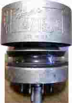
The RF output tube for the Clegg Zeus is a 4X150A / 7034 external anode tetrode.
Capable of plate dissipation of 150 watts, the tube requires forced-air cooling which is supplied by a relatively quiet squirrel-cage fan in the Zeus. Zeus RF output is rated at about 125 watts.
Repairs
After cleaning the filth off the Zeus RF and power supply/ modulator chassis, I read the downloaded manual copy from 6mtr.com. I then proceeded to do safety checks, replaced the power supply fuse with the proper size, checked transformer continuity, and cleaned all of the switches, controls, and the Jones cable connectors with contact cleaner. I cleaned and painted the transformers and power choke.
I reformed the electrolytics with an external source, (Heathkit PS-4 variable regulated power supply). I found that I needed to disconnect the three series electrolytics for the plate voltage to reform them individually and evenly. After reforming, I verified that the three were evenly dividing the voltage from my external source.
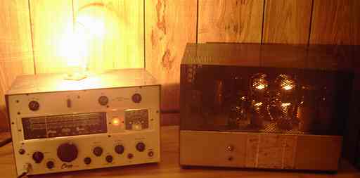
I pulled the rectifier tubes prior to plugging the unit in. The bias supply with its selenium rectifier proved to be in good order, the tube filaments were OK and the cooling fan was working. This was my first experience with the brightly-lighted 811A modulator tubes. The 811A tube definitely has bright filaments.
I next powered the unit with just the lower B+ rectifier in. This powers the unit for all stages except the final.
Open meter
I was unable to get any grid current at the first tune-up switch setting. Upon checking the meter, found it to be open circuit. I removed the meter and opened it. The rear hair spring of the movement was disconnected. I tried repairing the meter by soldering the spring onto its connector. Although the meter was functional after repair, the movement took more than 3 mA to come to full scale and was no longer linear. Apparently part of the rear spring had "disappeared" and the resulting smaller spring was a bit too taut. No adjustment would solve the problem. I found a Motorola meter in the junque box that was a near-match in size. It had a 200uA movement at 120 ohms. Bridging it with an 8.2 ohm resistor brought it to 3 mA full-scale. I removed the scale and the clear plastic front from the bad Clegg meter and mounted them onto the replacement. I used a fine brush to paint the Motorola meter's black pointer white so it could be seen on the Clegg meter's black scale.
While checking the meter, I also replaced the 10 ohm resistor in the RF power output tube (PA) metering circuit. The original had increased in value to 12.5 ohms. Using a low voltage variable bench supply with a few Christmas tree low-voltage lights for a load, I verified that the meter circuit would properly measure PA plate current with the replacement resistor.
Even with the replacement meter, I was still unable to get any meter reading on the Tune 1 position, measuring grid current on the driver tube, or Tune 2, grid current for the final PA tube.
This was my first encounter with external anode forced air power tubes. I had no means of testing the tube. Although I could read the proper frequency coming from the multiplier tube with a counter, I was not sure that the driver tube was doing its job. Swapping the driver with an identical tube used for the 2 meter doubler made no difference. Using a 10 to 1 divider probe and a Tektronix scope capable of 150 MHz, I verified that a proper 6 meter (at 51 MHz) signal was present at the driver. However, the signal level was low. While the scope was connected, I tweaked the multiplier coil. The RF voltage read by the scope quickly climbed to a much greater level at the driver grid. I was now able to see grid current on the driver grid (Tune 1 switch position) with the meter. However, the meter still refused to budge when switched to the "Tune 2" position for PA tube grid current despite the scope showing plenty of voltage at the driver plate.
With nothing left to test except the PA tube, I pulled the tube and, using a VOM, found that the screen grid and input grid were shorted. Bad PA tube.
A replacement Eimac 4X150A / 7034 was found at reasonable cost on ebay. Installing it finally enabled the meter to see grid current on the PA tube. Tuning up the final brought a satisfying amount of RF to my clear glass light bulb dummy load. I purposely kept the load control throttled back a bit for fear of burning out the bulb. A Zeus is capable of about 125 watts RF output when loaded properly.
Update
This Zeus was lonesome for its receiver mate and has left my QTH for a new good home to join the Interceptor.
The Morrow 3BR-5 converter was the previous item on the bench.