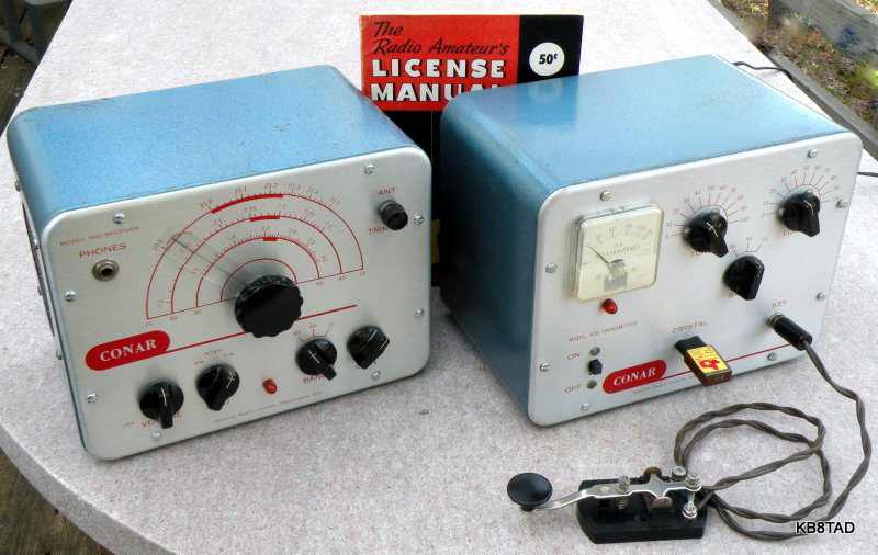
Conar Twins - Ham Receiver and Transmitter
The Conar 400 transmitter and Conar 500 receiver were sold as kits by NRI, the National Radio Institute. The pair are affectionately known as the Conar Twins.
The main business model for NRI was correspondence courses in radio and electronics. They also sold some decent test equipment under both the NRI and Conar brands. Several pieces of test equipment are the same form factor as these twins. Click on this link to see one such example, the Conar Model 230 Signal Tracer repaired earlier. The Twins were NRI's only venture into ham radio gear. NRI obviously re-used some of their standard test equipment components such as the cabinets, knobs and styling which match that of the signal tracer shown at the link. To my eye, the Conar twins look more like modified test equipment than does any other brand of ham radio receiver and transmitter.
Offered as a package
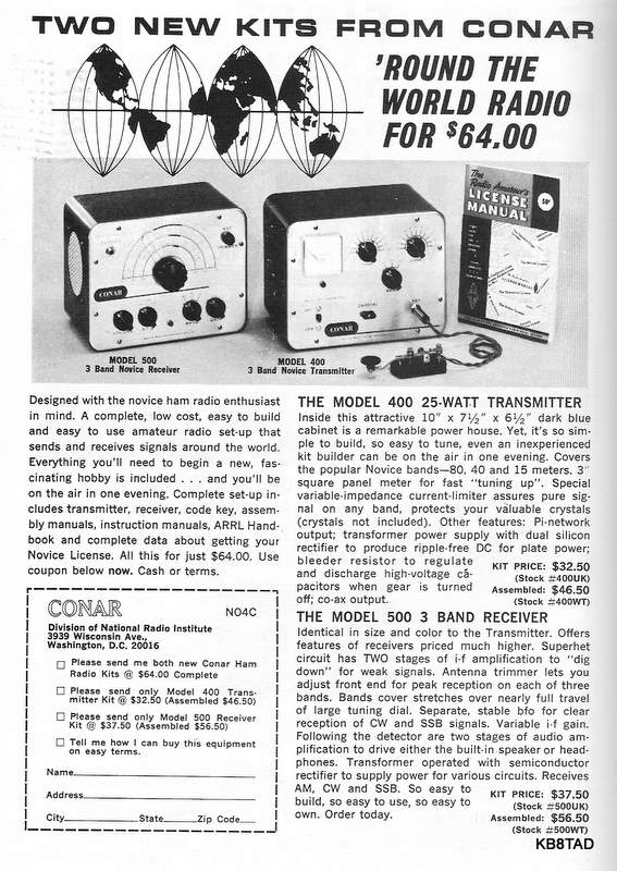
The Conar twins were advertised as kits in the ad shown above from the 1965 ARRL Handbook . The package included a Morse code key, instruction manuals, and an ARRL license manual for a total price of $64.
The Conar transmitter
The Conar 400 transmitter uses a single tube, a 6DQ6, as a crystal-controlled powered oscillator and can transmit CW (continuous wave for Morse code) on the 80, 40, and 15 meter ham bands. As a relatively simple transmitter, it is known for having a signal that has a bit of character, a variation in tone obvious on the receiving end.
The Conar receiver
The Conar 500, on the other hand, is a nicely designed 4 tube receiver of decent performance which covers the same 80, 40, and 15 meter ham bands. The receiver uses a 6BE6 converter, a 6BZ6 as IF amplifier, a 6U8 as second IF amp and BFO, and another 6U8 as combination audio amplifier and audio output. It uses only 18 watts of power allowing for a small power transformer. A half wave selenium rectifier provides B+. The Conar with its ham-band-only coverage was probably the best bargain receiver available to new hams with a novice license in the mid 1960s, since the typical receivers in the $30 to $50 price class were low-end general coverage sets primarily intended for short-wave listening. The Conar 500 could easily outclass them on the ham bands.
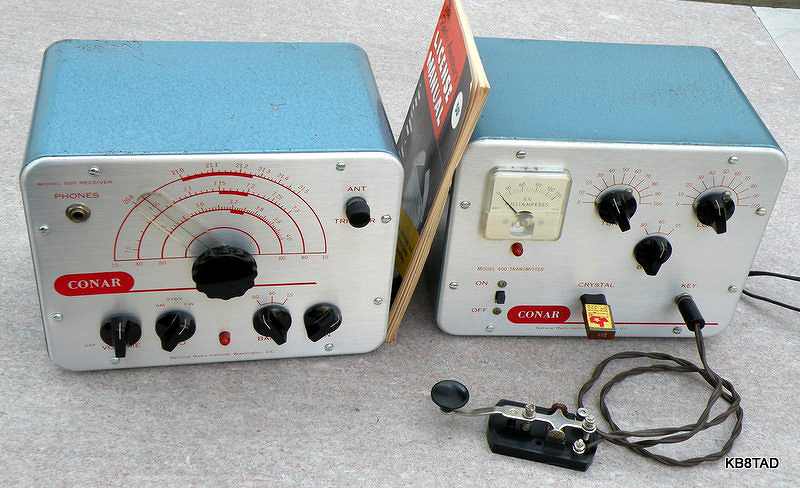
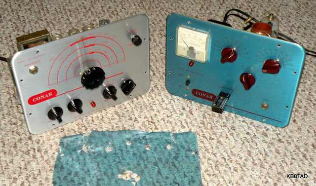
Blue faced
The twins still had the protective blue vinyl plastic on the front panels when purchased at a hamfest. I was concerned that removal might damage the silk screening after so many years.
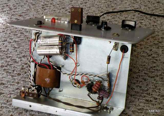
Transmitter Repairs
Both of the units had the controls cleaned with contact cleaner. The electrolytics easily reformed. All the other capacitors were either ceramic or mica and in good condition.
The transmitter was tested with a 40 watt dummy load bulb. It actually worked but was very slugglish. The action seemed to vary depending upon which crystal was used. It hesitated at times, requiring me to tap the key for several strokes before transmitting at resonance. I noticed that the small pilot bulb in series with the crystal did not light at all. I thought that possibly the light bulb assembly might be shorted or have the wrong bulb. I checked for those possibilities and even swapped a 60 mA bulb like that seen in similar transmitters. Still no light.
I also noticed that the loading capacitor seemed to need more capacity to properly load the 40 watt bulb. I temporarily added a 100 pF cap to the loading capacitor. That made a noticeable difference to the loading. I stared at the schematic a bit, and then it dawned on me. The loading variable cap was already bridged with a 1000 pF fixed cap. Therefore the extra 100 pF should have made almost no difference. I began to wonder if the builder had mistakenly swapped the only two mica caps in the transmitter, the 100 pF grid cap and the 1000 pF loading cap. Those mica caps were just about the same physical size. One cap was labeled 101J and the other 102J. Such a mistake would be easy for a novice kit builder to make.
Swapping the micas
Sure enough! The mica caps had been swapped. Switching them back solved the problems I had been observing. With the swapped mica cap mistake, it is likely that this Conar 400 was never used on the air.
Reducing crystal current
The lamp in series with the crystal is a number 40 pilot lamp rated at 150 mA at 6.3 volts. After repair, it lit up to roughly 100 mA or more making me fearful of damaging my ham-band FT-243 crystals.
Why the light bulb? It is a current limiter for the crystal because the bulb will burn out if pushed beyond a maximum of about 150 mA. Notice that the Conar ad above seems a bit optimistic in describing its purpose. "Special variable impedance current limiter assures pure signal on any band, protects your valuable crystals...". As hams would say, "Hi Hi", or text LOL.
To my thinking, crystal current at well over 100 mA seemed excessive. I wanted less crystal current. Since the oscillator had worked although sluggishly with almost no crystal current when the grid cap had mistakenly been 1000 pF, I decided to experiment with adding some capacity to the now correct 100 pF grid cap. After trying several values of capacitance, I ended up adding a 70 pF silver mica in parallel with the 100 pF mica shown in the schematic. That reduced the crystal current somewhat without affecting operation.
Taming the tone
Since the transmitter is known for a bit of "youp" (a minor variation in the transmit frequency noticeable as a tone change on the receive end), I tested the transmitter using the dummy load and monitoring with my Kenwood transceiver, antenna disconnected. Loading the transmitter to about 70-75 mA gave a satisfactory output for the dummy load bulb and very acceptable note to the audio. Being off resonance or loading with more current to 85-90 mA caused noticeable variation in the note. The no load B+ with my line voltage was 386 volts. The B+ voltage at a load of 75 mA was 333 volts. It's interesting to observe that the input to the 6DQ6 at that level was almost exactly 25 watts. I also tried a smaller plug-compatible 6BQ6. That reduced crystal current a bit more and provided a decent note when loaded to 70 mA, an input power of about 23 watts.
Taming the tone follow-up tests
After my repairs and initial tests on the Conar 400, I read the article by Mike, KK6GM, in the July 2001 QST magazine on the Conar Twins. He had not yet modified or tried out methods to improve the 400. I decided to try one of his suggestions to stiffen the power supply by clipping in a known-good 150 uF 400 volt electrolytic I had liberated from a computer power supply. That did indeed help and I found I could load the transmitter a bit more than the 75 mA in my previous result. However, what it allowed was a bit longer Morse "dah" before the inevitable tone change, a predictable result since the added cap provided a bit larger current reservoir and held off the B+ droop a bit longer as was readily observed on my voltmeter.
I also tried to see what would happen if the screen grid supply was rock solid. I disconnected the screen power lead from the voltage divider and fed it independently with my Heath PS-4 regulated supply. That did make a difference. I could load the Conar 400 to 90 mA by simply setting the regulated voltage supply at about 200 volts with a cleaner note. However, the Conar's power supply itself still provided some "youp" due to the difference between B+ voltage at load/ no-load. Since the overall cause seemed to be the B+ drop, perhaps a better solution for a powered oscillator would have been choke input for the power supply. However, adding choke input to the Conar would reduce the maximum B+ voltage by about 30% and therefore reduce power output.
For now, I decided to just leave the Conar as designed and limit the loading to 75 mA which, with the increase in AC voltage at the power socket, still allows the 400 to produce a reasonably good signal at its designed input wattage.
Receiver Repairs
The receiver was working quite well as purchased. While reading about the receiver on the internet, I noticed a complaint about too much hum in the audio. One solution mentioned by Bry, AF4K, was to swap the half-wave selenium rectifier with a full wave bridge. I decided to make that modification, replacing the selenium with a terminal strip and a bridge rectifier also liberated from a defunct computer power supply. I added a series resistor to make up for the more efficient diode bridge and also a powerline fuse. I used a scope to check for ripple voltage in the power supply B+. The bridge rectifier cut the ripple voltage in half. Since I had added a series resistor, I decided to also add another electrolytic section, making for a double pi filter. That really reduced audio hum to almost nothing on AM even with the volume control at maximum. However, the hum persisted when the BFO was turned on. I temporarily fed the filament chain with DC, thinking there might be some heater-to-cathode leakage in one of the tubes. No change.
The alignment needed some tweaking for both the IF chain and the RF adjustments. While following the alignment instructions for tweaking the BFO, I noticed variations in the hum level. After adjusting the BFO coils according to the manual and turning the RF gain all the way down, the only signal left was hum. I then re-tweaked the BFO coils hoping to minimize the hum. I was able to do that with only minor adjustments. Turning the RF gain back up gave a good BFO level with very little hum.
Another concern expressed on the net was the small speaker in a metal cabinet that was touching or nearly touching an IF transformer. I placed a small self-stick felt circle on the rear of the speaker and did not notice any noise due to metal contact. Another option I used was to simply plug an external speaker into the headphone jack which is wired for low impedance and cuts out the internal speaker.
Perceptions of the Conar Twins
For the money in 1965, I would rate the Conar receiver a "Best Buy" since it is still quite usable on the ham bands when compared to about any other receiver sold near the $64 price quoted for the entire Conar package. The transmitter shows the typical weakness of a single tube powered-oscillator. It is acceptable when conservatively operated and is in the same league as the ARRL Handbook homebrew "slatboard", the Ameco AC-1, and similar transmitters. It should only be used with robust crystals. In the hands of a skilled operator, the Conar Twins are a very usable pair that can give a ham the satisfaction of successfully "hunting with primitive weapons" (for QSO's of course!).
3-28-10
The Navy ARB Aircraft Radio Receiver was the previous item on the bench.