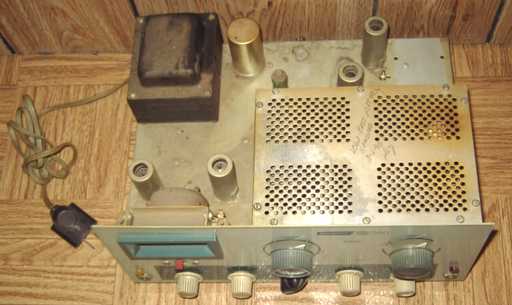
A well-used DX-60 with the typical layer of chassis dust and dirt.
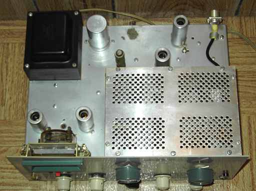
After cleaning
The Heathkit DX-60 is a kit-built CW and AM transmitter introduced in 1962. It replaced the DX-40. Designed for the 80 to 10 meter ham bands, the DX-60 uses a 6146 final RF tube for 90 watts peak power input controlled carrier AM and CW, according to the manual. This example came with a 6146B. A neutralization stub is included with the DX-60 circuitry.
A plate current of 120 mA on the meter corresponded to the 75 watt maximum input allowed a Novice ham in the 1960's. A front-panel switch can select several crystal positions or external VFO. Heath offered the HG-10 as a matching VFO and the HR-10 as a matching receiver. Price of the DX-60 in the Heath ad in the1962 Radio Amateur's Handbook was $82.95. The price dropped to $79.95 in 1963.
Try this link for Heath catalog information on the DX-60.
A well-used DX-60 with the typical layer of chassis dust and dirt.
After cleaning
Repairs
I reviewed the schematic and did the usual safety checks, making sure the fuses were proper (but see below), checking for any power line to chassis leakage, and checking for sufficient resistance in the B+ line. I also cleaned the unit thoroughly with waterless hand cleaner and soft toothbrushes. The switches and the grid drive control were cleaned with contact cleaner and checked for function.
Penciled notes under the chassis indicated that the original owner had replaced the power/ function switch and the axial electrolytics in the B+ circuit. Both repairs had been completed in the mid 1960's. A note on top of the chassis stated that in 1990 the low pass filter had been removed. The low pass filter and antenna coax were still missing when I obtained the transmitter. This likely meant that the transmitter had not been used since that time. I wired a direct coax connection to an SO-239 antenna connector. If necessary, I can add an external low pass filter. With television primarily coming over cable and satellite, low pass filters are not as necessary as they were in the days of weak-signal TV antennas.
I used an external Heath variable power supply to reform the electrolytics. While the axial electrolytics that had been replaced by the original owner were fine and easily reformed, the chassis mount electrolytic had considerable leakage and did not reform readily. I opted to replace it with an a new old stock part that easily reformed and fortunately had the same dimensions as well as values. I also looked for possible bad solder joints and re-did one of the connections on the function switch that had been replaced.
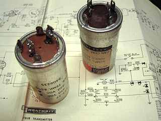
original on the left - NOS Sprague replacement on the right
Testing
I installed a 40 meter crystal and then preset the transmitter and connected a lamp dummy load per the instructions in the manual. Powering the set in tune-up and setting grid current revealed that the crystal socket and the switch position did not match. Apparently the original owner had made a mistake and reversed the crystal socket order relative to the switch. I set the switch to the active crystal. After properly setting grid drive, I switched the set to CW and was easily able to get full output from the transmitter. This was somewhat of a surprise since the 6146B RF output tube had tested on the weak side according to the stingy meter of my TV-7 tube tester. The controlled carrier modulation also worked well.
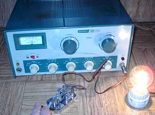
Full output into a dummy load
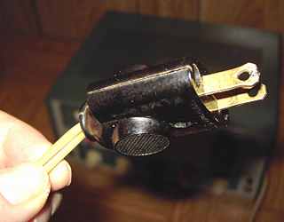
Modifying the power plug for safety
This unit had the original DX-60 power plug that is a safety concern. Both sides of the power line are fused. This allows the neutral side to be opened during a fault allowing the hot side the possibility of leaking to the chassis. Modern safety codes do not allow the neutral to be opened by a fuse or switch. The power cord can be replaced with a proper 3 wire grounded power cord with a chassis-mounted fuse.
Because of the presence of feed-through capacitors in the DX-60 power input, I wanted to keep the fuse element ahead of the feed-through caps. With that need as well as wanting to keep the transmitter as original as possible, I opted to modify the original power plug to make it polarized. I checked to see which side of the power connection was the unswitched side that should be the neutral. Then, using a pair of diagonal cutters, I cut the tip of the plug's neutral blade causing the blade tip to expand. I expanded it a bit more and soldered the resulting gap in the tip, using a file to remove extra solder. The result was a plug that can only be inserted in one direction. I removed the fuse from the neutral side and wired directly to the now-polarized neutral blade. The hot side of the plug still has the appropriate fuse.
Future mod reversal
The microphone connector on the transmitter had been replaced by a 3/16 inch phone jack. I intend to replace that jack with the proper Amphenol connector.