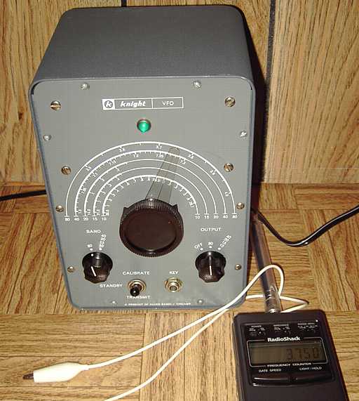
Frequency counter sniffing V-44 output at 3.750 MHz
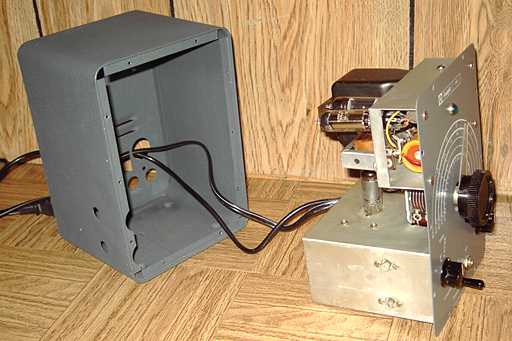
The Knight-Kit V44 VFO (Variable Frequency Oscillator) was a kit sold by Allied Radio. The catalog number was 83Y725. The copyright date in the manual is 1955. It uses a 6BH6 as series-tuned Clapp oscillator, 6AK6 as a buffer, 6X4 as rectifier and 0A2 voltage regulator. Unlike some competing models of the era such as the Heathkit VF-1, the Knight-kit has a built in power supply. The supply is mounted above the oscillator components to limit convection heat. The VFO specifies an RF output of approximately 10 volts.
According to the manual introduction, it is
Repairs
The hamfest seller had said the VFO "had some problems". The VFO came without tubes and had both the power cord and the coax cable cut short. The center lead of the existing coax had a bad solder joint on the terminal strip. That may have caused intermittent performance and led to the VFO's problems. I located tubes, replaced the coax with a flexible piece from an junked early cell phone, and connected a polarized line cord. Another questionable solder joint was reflowed. The switches were cleaned with contact cleaner.The tuning dial mechanism was stiff causing the dial to hang up at various points. A tiny bit of lubrication solved the problem. After the usual safety checks, I powered the unit slowly to reform the electrolytic.
The manual is available from BAMA in pdf form. I have an original paper version also. I looked to see what frequency the VFO uses as its fundamental because the upper frequency range junped from 3.6 to around 5 MHz, no-where near the expected output. The manual does not clearly state fundamental frequency. I used a grid dip meter to see if I could determine the fundamental but could not get a dip in either the 40 meter or 80 meter band. By measuring the values of the variable caps and the main inductor and calculating resonance, it dawned on me that the fundamental frequency of this VFO for both ranges was in the 160 meter band. The VFO doubles that and the output for both ranges is in the 80 meter band broadly tuned by the buffer coils. The original 5 MHz reading was caused by tripling in the output. I tried to tune the output to 7 MHZ as measured by the dip meter but the coil would not go that high. I then assumed that an 80 meter range was appropriate even for the 40 meter and higher ranges. The main difference is switching in either the (approximately) 10 pF or the 25 pF section of the main variable to achieve proper band tracking.
An Eico 730 modulator/ driver was the previous item on the bench.